I do not see a capacitor of 1 - 10 nF on pin 5 to ground for decoupling
.Pin 5 (Control Voltage): This pin allows direct access to the 2/3 V+ voltage-divider point, the reference level for the upper comparator. It also allows indirect access to the lower comparator, as there is a 2:1 divider (R8 - R9) from this point to the lower-comparator reference input, Q13. Use of this terminal is the option of the user, but it does allow extreme flexibility by permitting modification of the timing period, resetting of the comparator, etc. When the 555 timer is used in a voltage-controlled mode, its voltage-controlled operation ranges from about 1 volt less than V+ down to within 2 volts of ground (although this is not guaranteed). Voltages can be safely applied outside these limits, but they should be confined within the limits of V+ and ground for reliability. By applying a voltage to this pin, it is possible to vary the timing of the device independently of the RC network. The control voltage may be varied from 45 to 90% of the Vcc in the monostable mode, making it possible to control the width of the output pulse independently of RC. When it is used in the astable mode, the control voltage can be varied from 1.7V to the full Vcc. Varying the voltage in the astable mode will produce a frequency modulated (FM) output. In the event the control-voltage pin is not used, it is recommended that it be bypassed, to ground, with a capacitor of about 0.01uF (10nF) for immunity to noise, since it is a comparator input. This fact is not obvious in many 555 circuits since I have seen many circuits with 'no-pin-5' connected to anything, but this is the proper procedure. The small ceramic cap may eliminate false triggering.
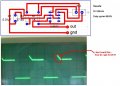
I see where you're going eblc, you're thinking inductance. The 555 produces some clean edges, so you could be generating an inductive kick from the long lead length.
 Facebook
 Google
 GitHub
 Linkedin