SPI clock speed 18F4620 Oshonsoft

Thread Starter

camerart

Joined Feb 25, 2013
3,724
Hi,
I'm programming an 18F4620 PIC, using Oshonsoft.
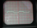
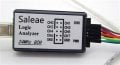
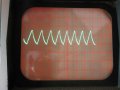
While trying to get SPI to work, I connected a Logic analyser.

In Oshonsoft the simulator uses a code line:
Define SIMULATION_WAITMS_VALUE = 1 'Comment in for SIM out for PIC
to speed it up to a sensible speed.

I've found that the Analyser only works when the PIC has the LINE commented in, so a 1x second LED flash flashes 1000x too fast.

I've been trying different clock settings, all failed. Now I'm looking at OSCCON and OSCTUNE. The program clock is set to 8Mhz and the PLLEN = 1, so 4x faster =32MHz
Can someone help me set these too registers correctly please?
Camerart.
 

ericgibbs

Joined Jan 29, 2010
18,766
hi C,
If I understand your query correctly.
Define SIMULATION_WAITMS_VALUE = 1 'Comment in for SIM out for PIC
This command is used in simulation, so that the coded delays are reduced in time and the sim will run faster in the IDE.
Otherwise due to the slow execution rate of the simulator, the sims would be very slooooow.

When you REM it out
'''Define SIMULATION_WAITMS_VALUE = 1 'Comment in for SIM out for PIC
The delays written in your code will be the correct real time delays, suitable for a programmed PIC.

We have have already covered setting the internal clock to 8MHz and the setting the PLL*4 enable bit, so that the internal clock is 32MHz.

Is this what you are asking.?
E
EDIT:
Do you have these code lines in the program Header.?

Define CLOCK_FREQUENCY = 8
OSCCON = %01110010 'internal 8Mhz clock
OSCTUNE.PLLEN = 1 '*4 PLL enabled so Fosc = 32MHZ
 
Last edited:

Thread Starter

camerart

Joined Feb 25, 2013
3,724
hi C,
If I understand your query correctly.
Define SIMULATION_WAITMS_VALUE = 1 'Comment in for SIM out for PIC
This command is used in simulation, so that the coded delays are reduced in time and the sim will run faster in the IDE.
Otherwise due to the slow execution rate of the simulator, the sims would be very slooooow.

When you REM it out
'''Define SIMULATION_WAITMS_VALUE = 1 'Comment in for SIM out for PIC
The delays written in your code will be the correct real time delays, suitable for a programmed PIC.

We have have already covered setting the internal clock to 8MHz and the setting the PLL*4 enable bit, so that the internal clock is 32MHz.

Is this what you are asking.?
E
Hi E,
The program runs correctly in the SIM with the LINE commented in.
The program runs correctly LIVE with the LINE commented out.

With the program running correctly LIVE, the LED flashes once/sec as programmed, but when testing SPI my Logic analyser doesn't work. If I comment the LINE IN so the LED flashes 1000x toooooo fast, then the Analyser doesn't work.
C.
 

ericgibbs

Joined Jan 29, 2010
18,766
Hi E,
While I check the speed, note that the analyser is working at 1000x faster, but not the slower correct speed.
C.
hi C,
I don't understand what you are asking.?
You say, in the Sim and also the programmed PIC work as expected, but the analyser doesn't.?
E
 

Thread Starter

camerart

Joined Feb 25, 2013
3,724
hi C,
I don't understand what you are asking.?
You say, in the Sim and also the programmed PIC work as expected, but the analyser doesn't.?
E
Hi E,
Correct! only the Analyser isn't working, so I can't read the SPI readings, unless I speed up the PIC by commenting in the LINE.
EDIT: It's possible I haven't got the OSC settings correct. Although the LED does flash at the expected speed.
C
 
Last edited:

Thread Starter

camerart

Joined Feb 25, 2013
3,724
Hi,
I've found a clue!
Here is an image of when the PIC is set to be 1000x faster. Note the initial triggers are LOW to HIGH.
When set to the correct speed, the same applies, but I don't get the readings shown bottom right. I was making the assumtion that it works when running fast, but it's working in both instances.

Sometimes I get this error line: "The initial (idle) state of the CLK line does not match the settings" So I've got to find out how to correct it.

There is a ENABLE LINE. NOTE: This may be incorrect! SPI uses an ENABLE LINE when a PIC is being used in SLAVE MODE. I have it connected to the MODULE CHIP SELECT, so I've got to figure this out.
C.
 

Attachments

Thread Starter

camerart

Joined Feb 25, 2013
3,724
Hi,
I set up another PCB with only a HMC5983 Compass module and an HC-12 radio module with an 18LF4520 PIC at 8MHz

Here is a screenshot of the Logic analyser and the received signal on a Terminal:

Thias shows both working, so remembering that the problem is a PCB with an 18F46K20 PIC, which is quite likely to be the problem.

Next! Try this program on the 18F46K20 PIC, and see what happens.
C.
 

Attachments

Thread Starter

camerart

Joined Feb 25, 2013
3,724
hi C,
On the jpg image post #9, what is the purpose of the repeat setting of the HC12 channel, in the program.?
E
Hi E,
I took an older program, that had compass and radio, only to check that at the correct speed, the logic analyser works.
The program was incidental.

Switching back to the 'real' PCB, and putting the program on with the incorrect PIC, has messed up the programmer. This has happened before, I'm sorting it out.
C
 

ericgibbs

Joined Jan 29, 2010
18,766
hi C,
As you may recall, if you ever need to SET a parameter in the HC12, via the Serial input, the SET pin must be Low, ie: 0v
E
 

Thread Starter

camerart

Joined Feb 25, 2013
3,724
hi C,
As you may recall, if you ever need to SET a parameter in the HC12, via the Serial input, the SET pin must be Low, ie: 0v
E
Hi C,
For setting the HC-12 I have a set wire/PIN, plus a push button on the radio to GND, in case the wire isn't working in the program.
As you can see, from the last image, showing the Logic analyser and the HC-12 received DATA.
Thanks,
C.
 
Last edited:

Thread Starter

camerart

Joined Feb 25, 2013
3,724
Hi,
Still confused! I've tried many different oscillator settings, and still not getting the correct result.

I switched the CLK OUT ON in the Config, and here is an oscilloscope reading. It was set to 0.1US, which I believe is 10 MHz. Does this tell us anything?
Note: The LINE on my old oscilloscope isn't full width.
C
 

Attachments

ericgibbs

Joined Jan 29, 2010
18,766
hi,
IF the scope is calibrated it shows a cycle every X scale graticule, which should be equal to 0.1uS per division ie: 10MHz.
You do not show the Y axis scaling.?
Also you should use a *10 scope probe.?
E
 

ericgibbs

Joined Jan 29, 2010
18,766
hi,
If you have time set the internal osc to 8MHz, with NO *4 PLL and repeat the scope measurement.
You should see a waveform period of t= 1/8MHz ie: 0.125uSec

E
 

Thread Starter

camerart

Joined Feb 25, 2013
3,724
hi,
If you have time set the internal osc to 8MHz, with NO *4 PLL and repeat the scope measurement.
You should see a waveform period of t= 1/8MHz ie: 0.125uSec

E
Hi E,
Oscilloscope last calibrated 1988 :)

INTOSC 8MHz
No X4 PLL

OSC set to X10
X= 10MHz/DIV
Y= 1V
 

Attachments

ericgibbs

Joined Jan 29, 2010
18,766
hi C,
If the scope time base is set the same for both those images, ie: 0.1uSec/dev
I would say the top trace is 4 times faster than the lower trace.

If the lower trace is 8MHz, the top trace is 32MHz.
E
AA1 17-Oct-18 15.39.gif
 

Thread Starter

camerart

Joined Feb 25, 2013
3,724
hi C,
If the scope time base is set the same for both those images, ie: 0.1uSec/dev
I would say the top trace is 4 times faster than the lower trace.

If the lower trace is 8MHz, the top trace is 32MHz.
E
View attachment 161790
Hi E,
1/ I included OSCTUNE.PLLEN = 1 'OSCx4 No difference in the reading. I've been finding that PLLEN X4 hasn't worked!

2/ I changed Define CLOCK_FREQUENCY = 8 to 32MHz, No difference in the reading, but the LED flashes approx 4X slower.

I've been down this path before, regarding oscillator and timings.
There are a number of questions:
How do:
Define CLOCK_FREQUENCY =, HFINTOSC, OSCCON and OSCTUNE affect the programs. I've been working through them all, but not been able to set them correctly.
C
 

jjw

Joined Dec 24, 2013
823
Define clock_frequency = tells to basic compiler what the real frequency is, which is set in oscillator settings.
The compiler uses this information at least in software delays WaitUs, WaitMs, maybe in other software based timings.
 
Top