Facebook
 Google
 GitHub
 Linkedin
This is a comprehensive question and I don’t where it will end.
I am new to deal with spectrum analyzer but worked for 3 years with the oscilloscope.
I have a new Rigol DSA815 spectrum Analyzer and it didn’t come with any probe. I searched upon probing for the spectrum analyzer. It is definitely not the oscilloscope probe.

One my search I come with this conclusion:
1- Probing in spectrum analyzer requires the impedance of the probe to be equal to 50? to match the spectrum analyzer input impedance.
2- The RF input is N male, many adapters (like N male to BNC) have a 50? resistor too.
3- When probing to the spectrum analyzer you have to take care of the output resistance of circuit under test as not to load it.
4- Co-axial cables are used for probing purposes in Spectrum analyzers.
What I want to measure:
We have a power line communication energy meters that have suffered from poor communication. It works in a range of 122 KHz.
As a beginning, we have noticed that if there are many Fluorescent lamps have a PFC capacitor in the input which will attenuate the PLC signal for sure and it will affect the communication. But this has to be measured accurately.

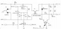
I am intending to make a PLC decoupling and filter circuit to measure the amplitude of the transmitted signal with the lamp switched ON and OFF with the spectrum analyzer.
What is the consideration that should be taken to probe the signal under study?
Is my approach is reasonable or it is not applicable at all?!
I am new to deal with spectrum analyzer but worked for 3 years with the oscilloscope.
I have a new Rigol DSA815 spectrum Analyzer and it didn’t come with any probe. I searched upon probing for the spectrum analyzer. It is definitely not the oscilloscope probe.
One my search I come with this conclusion:
1- Probing in spectrum analyzer requires the impedance of the probe to be equal to 50? to match the spectrum analyzer input impedance.
2- The RF input is N male, many adapters (like N male to BNC) have a 50? resistor too.
3- When probing to the spectrum analyzer you have to take care of the output resistance of circuit under test as not to load it.
4- Co-axial cables are used for probing purposes in Spectrum analyzers.
What I want to measure:
We have a power line communication energy meters that have suffered from poor communication. It works in a range of 122 KHz.
As a beginning, we have noticed that if there are many Fluorescent lamps have a PFC capacitor in the input which will attenuate the PLC signal for sure and it will affect the communication. But this has to be measured accurately.
I am intending to make a PLC decoupling and filter circuit to measure the amplitude of the transmitted signal with the lamp switched ON and OFF with the spectrum analyzer.
What is the consideration that should be taken to probe the signal under study?
Is my approach is reasonable or it is not applicable at all?!