Spectrum analyzer input impedance

Thread Starter

MagnusG

Joined Mar 1, 2022
9
Hello

I am new using spectrum analyzers and have recently been doing a measurement to verify a 50 ohm input impedance (which it is supposed to be). From my measurement I conclude that it is higher, so i wonder if anyone can see if I am doing any mistake.

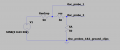
The test setup is as can be seen in the attached file.

I am expecting to get an amplitude of 315mV@30kHz (50% of the signal generator amplitude) on the SA input. This is, however, not what I am getting. I get a 420mV amplitude reading on the oscilloscope (resulting in a 100ohm input impedance on the SA) but the SA shows 315mV. So it seems that the SA is calibrated to compensate for the deviation in input impedance. Could this be the case? Or i am doing something wrong here?

/Magnus
 

Attachments

DickCappels

Joined Aug 21, 2008
10,153
What I would tell is with the analyzer off measure the input resistance with an ohmmeter. That should give you a clue, or increase the puzzlement.
 

KeithWalker

Joined Jul 10, 2017
3,063
The signal generator is designed to give you the specified voltage at its output connector, into a 50 ohm load (not 50% of it!).
You appear to have an accuracy problem with your oscilloscope. Is the vertical amplitude vernier set to the calibrated position?
 

tautech

Joined Oct 8, 2019
383
What brand and model ? Some SA's have 75 ohm inputs.
Also be aware SA inputs are very sensitive and can be easily damaged especially with low level DC.
Typical SA measurements are in dB not V or mV.
 

Thread Starter

MagnusG

Joined Mar 1, 2022
9
The signal generator is designed to give you the specified voltage at its output connector, into a 50 ohm load (not 50% of it!).
You appear to have an accuracy problem with your oscilloscope. Is the vertical amplitude vernier set to the calibrated position?
With this function generator the output voltage is not the specified one for a 50 ohm load. I have tried it with a load that I know is 50 ohm and i get the specified voltage divided by two. I have also measured the output voltage with the oscilloscope alone and then I get the specified voltage.
 

Thread Starter

MagnusG

Joined Mar 1, 2022
9
What brand and model ? Some SA's have 75 ohm inputs.
Also be aware SA inputs are very sensitive and can be easily damaged especially with low level DC.
Typical SA measurements are in dB not V or mV.
It is a Rigol RSA5065-TG.
The default input impedance is 50 Ω. To measure a 75 Ω device, you should use a 75 Ω to 50 Ω adapter (option) supplied by RIGOL to connect the analyzer with the system under test, and then set the input impedance to 75 Ω.

I have used 50ohm during my measurements with zero dc-offset. I displayed the values on the SA in mV because I wanted to be able to immediately compare it with the oscilliscope measurement. Otherwise I use dBm.
 

KeithWalker

Joined Jul 10, 2017
3,063
With this function generator the output voltage is not the specified one for a 50 ohm load. I have tried it with a load that I know is 50 ohm and i get the specified voltage divided by two. I have also measured the output voltage with the oscilloscope alone and then I get the specified voltage.
What function generator are you using? Maybe it is faulty.
 

drjohsmith

Joined Dec 13, 2021
852
I tried this and I get a overload as measurement result. I believe that the input is AC-coupled.
Word of warning

Input impedance of electronic equipment such as a spectrum analyser, is not always a real resistor

also,
a lot of meters, on resistance range,
output more then a few volts, especially if you start on a high resistance range.
and spectrum analysers are often rated to a few volts of input

If you put to high a voltage on the input, you will likely pop the spectrum analyser input
 

KeithWalker

Joined Jul 10, 2017
3,063
If you really want to check the input impedance of the analyzer, connect a signal to its input through a 50 ohm resistor. If the signal voltage across the resistor is the same as the voltage from the analyzer input to ground, then it is 50 ohms. If not, you can work out what it is by the ratio of the two signals.
I don't believe you have a problem. It appears that the anonymous signal generator's output is specified into a high impedance.
 

DickCappels

Joined Aug 21, 2008
10,153
If you do it with the power off, not power other than that supplied by the ohmmeter will have a chance of "burning" something. Just being cautious.
 

Thread Starter

MagnusG

Joined Mar 1, 2022
9
If you really want to check the input impedance of the analyzer, connect a signal to its input through a 50 ohm resistor. If the signal voltage across the resistor is the same as the voltage from the analyzer input to ground, then it is 50 ohms. If not, you can work out what it is by the ratio of the two signals.
I don't believe you have a problem. It appears that the anonymous signal generator's output is specified into a high impedance.
I don't see how this test would bring up something new but I have done it.

I get 25% of the specified function generator voltage across the 50 ohm resistor, 50% across the unknown SA input and 25% across the 50 ohm internal function generator impedance. This test does, as my previous one, suggest an SA input impedance of approximately 100 ohm.

I have attached a photo on my function generator.

DSC_0236.JPG
 

KeithWalker

Joined Jul 10, 2017
3,063
I don't see how this test would bring up something new but I have done it.

I get 25% of the specified function generator voltage across the 50 ohm resistor, 50% across the unknown SA input and 25% across the 50 ohm internal function generator impedance. This test does, as my previous one, suggest an SA input impedance of approximately 100 ohm.
NO!
You are doing it wrong and thoroughly confusing yourself. The function generator's output voltage is specified into a 50 ohms load. The indicated output voltage will not be accurate when you connect a resistor in series with the analyzer..Forget what the generator is telling you and make some actual measurements. If you measure across the resistor with the scope, you are grounding one side of the resistor through the scope ground. That will give you the full voltage across the generator;s output which is invalid..
With the scope, measure the voltage across both the resistor and analyzer. Then measure just across the analyzer input.
If you get the twice the voltage across the 50 ohm resistor and the analyzer as you get across just the analyzer, they are both the same impedance!


.
 
Last edited:

Thread Starter

MagnusG

Joined Mar 1, 2022
9
NO!
You are doing it wrong and thoroughly confusing yourself. The function generator's output voltage is specified into a 50 ohms load. The indicated output voltage will not be accurate when you connect a resistor in series with the analyzer..Forget what the generator is telling you and make some actual measurements. If you measure across the resistor with the scope, you are grounding one side of the resistor through the scope ground. That will give you the full voltage across the generator;s output which is invalid..
With the scope, measure the voltage across both the resistor and analyzer. Then measure just across the analyzer input.
If you get the twice the voltage across the 50 ohm resistor and the analyzer as you get across just the analyzer, they are both the same impedance!

"With the scope, measure the voltage across both the resistor and analyzer. Then measure just across the analyzer input.
If you get the twice the voltage across the 50 ohm resistor and the analyzer as you get across just the analyzer, they are both the same impedance!"
I measured just like that. With two oscilloscope probes. One across both the resistor and SA-input and one across just the SA-input. I did not get twice the voltage across the 50 ohm resistor and the SA as I got across just the SA. I measured the following ratio:

(50ohm resistor and SA voltage)/(SA voltage) = 3/2 = 1,5
 
Last edited by a moderator:

DickCappels

Joined Aug 21, 2008
10,153
When using "ordinary" scope probes you measure things with respect to ground, not across components, except when one lead of said component is grounded.

In certain cases you can float a scope so the the scope's ground connection can be referenced to some voltage or signal. This does not work well at high frequencies.

From your description I cannot understand what you measured.
 
Top