Facebook
 Google
 GitHub
 Linkedin
Hi, I'm an audio engineer by profession. I particularly interested in learning about the electronic side of the trade. I have been recently working on learning about filter circuits and cross over design. I'm competent with basic calculation like impedance etc. I'm just going through some circuit designs trying to figure out what does what
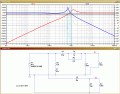
I have attached a screen shot of the cross over circuit which I'm going through (I sketched it myself as I couldn't find a schematic for the circuit). Couple of question
1. What is the use of the combination of R1 and C2?
2. What is the use of the combination of C3 and R2?
I would like to know a way of measuring the cut off frequency - I could get access to an oscilloscope and a spectrum analyzer at my old college. Would I need to connect a dummy load?
Is there a way measuring this at home? Recently I download a neat software called spectrum lab.
Very grateful for your responses in advance. Comments/advice on going further will really be appreciated.
Thanks
p.s I left out the values of some component as I couldn't figure it out (from the screenshot).
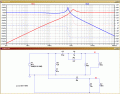
")