some advice from arduino to manufacturing

Thread Starter

flash01694

Joined Mar 7, 2018
26
Hello all,
I've been searching around the forum for a week or so now, and found some answers, but still, some questions remain!
By the level of expertise that appears to be shown here, I'm sure one (or several!) of you, can to point me in the right direction.

I have finished an arduino project and I think there is some business potential so I would like to translate into a permanent pcb design.
the design uses an arduino mini pro, an IR emitter and a gyro.

I have a decent arduino knowledge by tinkering with it but that is basically it, I have no specific electronic knowledge and 0 pcb design knowledge.

As far as I understood the steps would be:

- draw the schematics on eagle or a similar software
- send it to an online pcb manufacturer
- solder the parts on to it

what I have are really operative questions about the first part (the second and third seems pretty straightforward :)).

- which part of the Arduino do I need to translate to eagle and which part can I be omitted (for example I'm using 6 pins out of the 20+, so I'm guessing not every bit of the Arduino circuitry is needed)?

- once I have the pcb ready how do I flash the code onto it?

- Assuming I can't do it or that it will take me a long time to learn how to do it, if I provided the arduino schematics to someone who can do the pcb design would that be a fairly simple thing for a real pcb designer? and where could I hire someone who can do it?

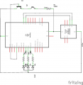
if it can help I can post the schematics here

thank you guys!
 

dendad

Joined Feb 20, 2016
4,637
It is worth while having a go with Eagle or some other program, to draw the board if you can. Then you can post a picture of your effort here and folks will help you refine it.
Here is a board I did with an Ardmino Mini Pro on it. I can but the Arduino cheaper than the parts so using the board complete as a componant makes sense to me.
20180516_FoneHome.jpg
The programming header is on the end of the Arduino for uploading the code using a USB to TTL lead.
On the spare part of the board I added a proto area and as there was a hardware mod upgrade, it proved very handy!
I installed all the Arduino pins but you could just connect the ones in use if you want.
Once again, I encourage you to have a go. It will work out well if you can build and service your own boards.
 

Thread Starter

flash01694

Joined Mar 7, 2018
26
It is worth while having a go with Eagle or some other program, to draw the board if you can. Then you can post a picture of your effort here and folks will help you refine it.
Here is a board I did with an Ardmino Mini Pro on it. I can but the Arduino cheaper than the parts so using the board complete as a componant makes sense to me.
View attachment 152600
The programming header is on the end of the Arduino for uploading the code using a USB to TTL lead.
On the spare part of the board I added a proto area and as there was a hardware mod upgrade, it proved very handy!
I installed all the Arduino pins but you could just connect the ones in use if you want.
Once again, I encourage you to have a go. It will work out well if you can build and service your own boards.
thanks for answering!

I skipped an important part on the question side however, I want to embed the microcontroller on the board I design, since I need it to fit in a very small space (40mmx 18mm), basically what I want to build is an arduino mini pro with far less i/o connections but which has a gyro and an infrared emitter, can that be done though eagle and similar software?
 

dendad

Joined Feb 20, 2016
4,637
Yes, you can design the board in Eagle (I have never used that. I use McCAD) and just put the Atlel processor, crystal, caps and regulator on board.
Make sure you add the in circuit programming pins so the Atmel can be programmed, (boot loader, unless you program it externally) and run out the serial pins if you want to then use the Arduino IDE and USB programming lead..
If you are able to use a DIP part, no programming hardware will be needed on your board as you can use an Arduino to do that. But is you need to save space, the SMT chip like on the Mini Pro, it will be needed.
Look at the Arduino Mini Pro circuit to see what is needed. If in doubt, put the circuit up and we can tell you what parts you can leave off.
Speaking of "off", I'm about to go off to bed :)
In the morning I'll see if there has been any more answers.
 

Thread Starter

flash01694

Joined Mar 7, 2018
26
just so you can understand how noob I am, I can tell you that I had to look up half of the terminology that you used xD

if I can manage to get a pcb done I still need to do the soldering part is that correct? I guess you need some kind of specialized equipment to solder a smt atmel chip or I can get it done alone?

ps: I'll upload the circuit tonight along with some doubts, thanks!
 

MrSoftware

Joined Oct 29, 2013
2,273
If you are in this for the business (and not the learning), then it might very well be cost and time effective to take your schematic and your requirements to someone with experience and pay them to double check your circuit and layout the board for you. Not only might they catch mistakes or omissions that might not be obvious to you, but they might also suggest improvements both for performance and for cost. There are a number of people here qualified to do it for you, or you can take it to a small development company. You will likely get much better pricing from a private individual who can do it in their spare time as companies have overhead to pay for. Be sure to specify in writing that you want to own the files and the final design when they are done, and also be very clear about exactly how you want it to behave. It's not that people aren't honest, it's that when you make something from nothing there could be endless possibilities for configurations and behavior, so both sides need a clear description of the finish line. Once complete, you can send the files to your favorite company to have the PCBs made. It's then up to you if you want to put the parts on yourself, or pay a company to do it for you. Good luck!
 

BobTPH

Joined Jun 5, 2013
11,514
An Arduino has a two stage programming process. The chip must be programmed with the boot loader, which can be done using ICP (in circuit programming). Then you have to download the program via a USB to serial converter. I don't know if you can get chips with the boot loader already programmed or not, as I am not an Arduino user.

You can leave any I/O pins unconnected, in which case you want to make them outputs so that noise does not get in through an unconnected input.

To make a PC board, you first draw a schematic. Then you lay out a board based on the schematic. I personally think Eagle is a horrible program for beginners. Others here use Kicad or Diptrace, which are a bit simpler to use. The easiest one I have used is Express PCB, but you are locked into them for manufacturing, it cannot write standard files used by another manufacturer.

I have been so frustrated with ALL the PCB CAD programs that I wrote my own.

Bob
 

shteii01

Joined Feb 19, 2010
4,644
First, I don't know where you are. If you are in a developed country (US, Australia, EU), then the smart thing to do is design the pcb to use SMD parts, send it to one of the Chinese pcb prototyping services where they will make the pcb and solder the parts on it. This will produce a professional looking product.

P.S.: remember, you have to place the code into the micro. are you going to trust Chinese with your code to program the micro or are you going to do it yourself. if you do it yourself, you will need some pins on pcb to attach a programmer to...
 

Thread Starter

flash01694

Joined Mar 7, 2018
26
first of all thank you guys for the huge response, really appreciate it!


If you are in this for the business (and not the learning), then it might very well be cost and time effective to take your schematic and your requirements to someone with experience and pay them to double check your circuit and layout the board for you. Not only might they catch mistakes or omissions that might not be obvious to you, but they might also suggest improvements both for performance and for cost. There are a number of people here qualified to do it for you, or you can take it to a small development company. You will likely get much better pricing from a private individual who can do it in their spare time as companies have overhead to pay for. Be sure to specify in writing that you want to own the files and the final design when they are done, and also be very clear about exactly how you want it to behave. It's not that people aren't honest, it's that when you make something from nothing there could be endless possibilities for configurations and behavior, so both sides need a clear description of the finish line. Once complete, you can send the files to your favorite company to have the PCBs made. It's then up to you if you want to put the parts on yourself, or pay a company to do it for you. Good luck!
you could say I'm in for both things, It is something I'm interested in and at the same time it might turn out to be a marketable product, in which case I would certainly pay someone more expert than me to do a better job. Also I really like the idea to make a piece of electronic from idea to finished product, so for now I'll try to see if I can make something decent on my own!

An Arduino has a two stage programming process. The chip must be programmed with the boot loader, which can be done using ICP (in circuit programming). Then you have to download the program via a USB to serial converter. I don't know if you can get chips with the boot loader already programmed or not, as I am not an Arduino user.

You can leave any I/O pins unconnected, in which case you want to make them outputs so that noise does not get in through an unconnected input.

To make a PC board, you first draw a schematic. Then you lay out a board based on the schematic. I personally think Eagle is a horrible program for beginners. Others here use Kicad or Diptrace, which are a bit simpler to use. The easiest one I have used is Express PCB, but you are locked into them for manufacturing, it cannot write standard files used by another manufacturer.

I have been so frustrated with ALL the PCB CAD programs that I wrote my own.

Bob
thank you, I started off with eagle and I was totally disoriented, I'll try either kicad or diptrace than!

First, I don't know where you are. If you are in a developed country (US, Australia, EU), then the smart thing to do is design the pcb to use SMD parts, send it to one of the Chinese pcb prototyping services where they will make the pcb and solder the parts on it. This will produce a professional looking product.

P.S.: remember, you have to place the code into the micro. are you going to trust Chinese with your code to program the micro or are you going to do it yourself. if you do it yourself, you will need some pins on pcb to attach a programmer to...
well I was already preparing for some very annoying micro soldering so if there is an option to do have an SMD pcb with the parts already soldered even for small orders that' s wonderful. I think I'm going to leave the ftdi connection holes in the design so I can save my code, thanks!


I'm attaching a sketch which I made with a software I just found (fritzing), the resistors are actually 100 ohms, it is an Arduino 3.3v, the gyro is an mpu 6050 and the rgb led is actually an rgb strip. nonetheless I think it gives a good idea, if you guys have any suggestions in any direction
I'm eager to learn!
 

Attachments

dendad

Joined Feb 20, 2016
4,637
It is a good idea to show your circuit.
A few of things,
There needs to be a base resistor for Q1. You may get away with it , leaving it out, but it is best to add one so the Arduino is not trying to apply 5V to a diode junction to ground.
The symbol for Q2 should be an LED.
One thing I add, like the white connector on my board, is an I2C interface to drive an LCD and that is used for debugging. This is pretty handy when getting your code working. Then the display is unplugged. The display code is still running but that does not matter.
Any programming headers can be left out, just add the holes. The trick is to have the holes not in line, but zig-zag them a bit so the headers are a firm fit when pushed in. That way, they do not stay with the board, but are plugged in when needed.
 

Travm

Joined Aug 16, 2016
363
Any programming headers can be left out, just add the holes. The trick is to have the holes not in line, but zig-zag them a bit so the headers are a firm fit when pushed in. That way, they do not stay with the board, but are plugged in when needed.
+1 for the programming header thing. That is going right in my toolbox.

As for PCB software, I started on expresspcb which I found super intuitive. I switched to kicad after I realized I had to use them for mfg. Only to realize later the board house I use can accept expresspcb files. Glad I forced myself to learn kicad though.
 

davidradio

Joined May 16, 2018
1
It is a good idea to show your circuit.
A few of things,
There needs to be a base resistor for Q1. You may get away with it , leaving it out, but it is best to add one so the Arduino is not trying to apply 5V to a diode junction to ground.
The symbol for Q2 should be an LED.
One thing I add, like the white connector on my board, is an I2C interface to drive an LCD and that is used for debugging. This is pretty handy when getting your code working. Then the display is unplugged. The display code is still running but that does not matter.
Any programming headers can be left out, just add the holes. The trick is to have the holes not in line, but zig-zag them a bit so the headers are a firm fit when pushed in. That way, they do not stay with the board, but are plugged in when needed.
Very good solution!
 
well I was already preparing for some very annoying micro soldering
In a sense, you don't solder in the conventional sense. The PCB manufacturer along with your PCB layout software can produce a stencil. This is essentially a laser cut piece of metal or polymer that is used as a mask to apply a solder paste with a squeegee.

Toaster ovens have been modified to create the temperature profile to solder the boards after the components have been placed.
 

dendad

Joined Feb 20, 2016
4,637
I purchased a SMT oven on Ebay, but modifying a toaster oven is a good idea.
The last time I used my SMT oven it incinerated the board :(
I've not had a look to see why. Imagine my "joy" to see smoke pouring out of the oven that had an iMac video board in it!
I do all my SMT soldering with a soldering iron anyway.
From Ebay, I purchased an Elmo Video Presenter. A bit like this Lumens brand one.
https://www.ebay.com.au/itm/Lumens-...869018?hash=item239ffacc5a:g:hkEAAOSw-YZa6xc6
It allows me to zoom in to a half a dozen 0.05mm pitch IC pins and view them on a monitor while soldering. An essential tool I think.
I find SMT boards are actually easier and quicker to build than through hole.
Don't let SMT scare you off. Have a try.
 
Last edited:

MrSoftware

Joined Oct 29, 2013
2,273
You can hand solder SMT chips yourself if the pins are exposed, and it helps to have the correct equipment. I linked a video below that shows an example. Notice how much flux he uses. Be liberal with the flux and cleanup later with alcohol, that will help a lot.

 
Top