Solid state relay project

Thread Starter

Clinton Brits

Joined Aug 8, 2015
16
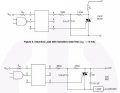
I spent the last week trying to complete an optocoupler - triac circuit in the hope I could control 220Vac.

I am now at a point where I'm was confident at an attempt but haven't been able to turn the load. I have gone through various sources and for the life of me I cannot understand why and to be honest I was expecting it to stay on and to not turn off.

I have uploaded the actual photo of the circuit and the connections. If anyone has succeded and would be so kind as to point out a connection error or pin error I would really appreciate it.

circuit_800x908.jpg
 

Thread Starter

Clinton Brits

Joined Aug 8, 2015
16
It doesn't turn on. That's why I connected the led on the optocoupler - I thought there migh have been a problem. I'm considering doing the circuit again on a breadboard to get it working before pulling out the solder iron.
 

Thread Starter

Clinton Brits

Joined Aug 8, 2015
16
Update : We have this circuit working with an optocoupler that does not have zero crossing but seems to not work with ones that do. I'm busy playing around with proteus that shows the same result so hopefully should have it puzzled out soon.
 

Thread Starter

Clinton Brits

Joined Aug 8, 2015
16
Zero cross switching types as this are usually easier/simpler to implement than the phase angle switching versions.
Max.
Could I ask you to check my understanding of the symbol of the triac and the pins of the device?

I have Live attached to pin one(MT1) and neutral attached to load attached to pin 2(MT2). The resistors are attached to pin1(MT1) and then to the opto and then the gate. Result : Nothing happens.

If I connect the resistors to Pin2(MT2) and then to the optocoupler that switches the gate we then have it working as usual!?

I love that it works but having something work and not knowing why is just idiotic.
 

Thread Starter

Clinton Brits

Joined Aug 8, 2015
16
Problem Solved! If anyone wants to try this the circuit I photographed was almost correct. Live still goes to pin 1. Neutral still goes to pin 2. The resistors that go into the optocoupler must connect the optocoupler and pin 2(Not 1!). The 50nf capacitor should connect the gate and pin 1.

This is really cool!
 
Top