Facebook
 Google
 GitHub
 Linkedin
Hello,
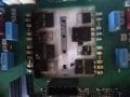
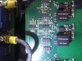
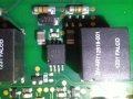
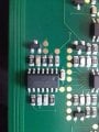
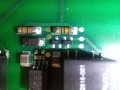
I'm trying to fix a solar inverter that has failed due to suspected high voltage.
I'd really appreciate if you would be able to help me identify these parts so I can order more. - I've googled for hours and have come to a dead end.
h3121441 (Optocoupler?)
bv-art12816-001
(1231 FALCO) (HF transformer?)
SMD 6525 ( Schottky diode?) rest on diode test = pin 1+ ,pin 2- = 0.294v pin 3+, pin 2- = 0.294
SMD R28 ( transistor?)
Pictures attached, let me know if any other pictures would be helpfull.
Thanks for your time,
Carl
Attachments
-
 226.6 KB Views: 14
 -
 223.7 KB Views: 11
 -
 229 KB Views: 12
 -
 208.4 KB Views: 12