Solar charger circuit for 6V/4.5Ah battery

Thread Starter

Ishan Jain

Joined Nov 12, 2016
100
Hello folks!

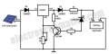
I am making a solar charge controller circuit for 6V battery and using a 3W solar panel to charge the battery but the output of the charge controller circuit is nil.The circuit diagram is attached. Please help! Its urgent.

Thank you
 

Attachments

ericgibbs

Joined Jan 29, 2010
21,397
hi IJ,
What are measured voltages on the LM317 In and Out.
Is the open circuit voltage of the solar panel approx 17v when exposed to bright sunshine.?

If you do getting working change the 1k pot to 2k
At full sunlight for 12V, 3W when the battery state is low, you should get about 250mA charge current.

E
 

Thread Starter

Ishan Jain

Joined Nov 12, 2016
100
hi IJ,
What are measured voltages on the LM317 In and Out.
Is the open circuit voltage of the solar panel approx 17v when exposed to bright sunshine.?

If you do getting working change the 1k pot to 2k
At full sunlight for 12V, 3W when the battery state is low, you should get about 250mA charge current.

E
Thanks Eric for your prompt reply. The input voltage on the LM317 In is around 9 volts whereas the output voltage is just 3.5 which is kinda surprising and the open circuit voltage of the solar panel is around 11.2 volts.
 

Colin55

Joined Aug 27, 2015
519
You have only got 250mA to play with. A 4.5 amp-hour battery can be charged at one tenth of its capacity (450mA) for days and days without any damage as the battery will absorb the charging current and not produce bubbles of gas. You will be charging the battery for a maximum of 8 hours a day at a maximum of 250mA so your battery will take this charging current indefinitely without "gassing." Each day will only deliver a maximum of 2 amp-hours and drawing more than this will gradually flatten the battery and drawing less than this will gradually charge the battery.
The only advantage of my design is the fact that the battery will start to charge at lower levels of sunlight, rather than that stupid circuit you are presently using.
 

Thread Starter

Ishan Jain

Joined Nov 12, 2016
100
You have only got 250mA to play with. A 4.5 amp-hour battery can be charged at one tenth of its capacity (450mA) for days and days without any damage as the battery will absorb the charging current and not produce bubbles of gas. You will be charging the battery for a maximum of 8 hours a day at a maximum of 250mA so your battery will take this charging current indefinitely without "gassing." Each day will only deliver a maximum of 2 amp-hours and drawing more than this will gradually flatten the battery and drawing less than this will gradually charge the battery.
The only advantage of my design is the fact that the battery will start to charge at lower levels of sunlight, rather than that stupid circuit you are presently using.
Sorry Colin the panel shown in the circuit is not actually that panel which I am using my panel is rated at 350mA current at maximum power and the short circuit current is around 390mA
According to you its safe to connect the battery directly to the solar panel. But still are there any chances of battery damage if I don't use any protection circuit?
 

dl324

Joined Mar 30, 2015
18,226
I am using my panel is rated at 350mA current at maximum power and the short circuit current is around 390mA
I doubt that the battery could be damaged by your solar panel.

You measured 390mA into a short. You won't get that at the MPP and you're unlikely to actually get 3W from the panel.

upload_2017-8-4_15-40-16.png

To convince yourself that you're not abusing the battery, you can add the disconnect circuit I mentioned.

If you want to reuse as much of the existing circuitry as possible, you'll need to use an N MOSFET between the battery and the solar panel negative terminals.

upload_2017-8-4_15-54-1.png
EDIT: Emitter connection corrected below.

You can reduce R1 and add an LED in series if you want a visual indication of active over voltage protection.
 
Last edited:

ericgibbs

Joined Jan 29, 2010
21,397
Thanks Eric for your prompt reply. The input voltage on the LM317 In is around 9 volts whereas the output voltage is just 3.5 which is kinda surprising and the open circuit voltage of the solar panel is around 11.2 volts.
hi IJ,
I suspect there is also a problem with your original circuit build.??
If the 1K adjust pot is set to 1K, check the 6.8Vzener.

With a 9V input to the LM317 and the battery disconnected you should get 6.4V out from the LM317.

The open circuit voltage of 11v is low for a 12V panel, can you confirm that you have a 12v Solar panel and not a 6v version.?

E
 

Colin55

Joined Aug 27, 2015
519
The open circuit voltage of 11v is low for a 12V panel, can you confirm that you have a 12v Solar panel and not a 6v version.?

You don't have to worry about all this "run-around" if you follow my advice. You are helping him move the deck-chairs on the Titanic.
 

Thread Starter

Ishan Jain

Joined Nov 12, 2016
100
The open circuit voltage of 11v is low for a 12V panel, can you confirm that you have a 12v Solar panel and not a 6v version.?

You don't have to worry about all this "run-around" if you follow my advice. You are helping him move the deck-chairs on the Titanic.
thanks for your advice Colin but as my panel output is around 9.5 volts most of the time so there is no need of LM317 therefore I altered the circuit by removing the LM317 section and keeping the other section intact and I think it is working fine.

Thanks a lot for your unconditional help .:)
 

Thread Starter

Ishan Jain

Joined Nov 12, 2016
100
hi IJ,
I suspect there is also a problem with your original circuit build.??
If the 1K adjust pot is set to 1K, check the 6.8Vzener.

With a 9V input to the LM317 and the battery disconnected you should get 6.4V out from the LM317.

The open circuit voltage of 11v is low for a 12V panel, can you confirm that you have a 12v Solar panel and not a 6v version.?

E
I removed the LM317 because the panel voltage is around 9.5 volts and the current is fine. Thank you for your help.
 

Thread Starter

Ishan Jain

Joined Nov 12, 2016
100
I doubt that the battery could be damaged by your solar panel.

You measured 390mA into a short. You won't get that at the MPP and you're unlikely to actually get 3W from the panel.

View attachment 132274

To convince yourself that you're not abusing the battery, you can add the disconnect circuit I mentioned.

If you want to reuse as much of the existing circuitry as possible, you'll need to use an N MOSFET between the battery and the solar panel negative terminals.

View attachment 132276
EDIT: Emitter connection corrected below.

You can reduce R1 and add an LED in series if you want a visual indication of active over voltage protection.
I got your point and thanks for your help and now I understand that my battery is safe.:D
 

pyroartist

Joined Oct 9, 2015
131
When connecting a panel directly to the battery is it wise to install a low voltage drop, Shottky diode in series to protect the battery from leakage current through the panel at night?
 
I doubt that the battery could be damaged by your solar panel.

You measured 390mA into a short. You won't get that at the MPP and you're unlikely to actually get 3W from the panel.

View attachment 132274

To convince yourself that you're not abusing the battery, you can add the disconnect circuit I mentioned.

If you want to reuse as much of the existing circuitry as possible, you'll need to use an N MOSFET between the battery and the solar panel negative terminals.

View attachment 132276
EDIT: Emitter connection corrected below.

You can reduce R1 and add an LED in series if you want a visual indication of active over voltage protection.
Haha, well yeah! I have almost killed my solar charger... Thank God I've read your post before doing something wrong. What a lucky day! :D
 
Top