SMPS switching problem

Thread Starter

roro36

Joined Sep 7, 2010
52
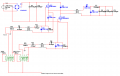
Design: Two swith flyback method switched mode power supply. Has about 45volts as the DC across the switches. I'm using PWM for a micro, through a mosfet driver, through a high side driver and onto the gate.
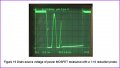
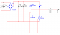
Results: The clear pulses in the last picture is of the gate source voltage/signal. It is correct. The next is the drain source voltage. Wrong, basically it should show a scaled inverted version of the input signal. As when the signal goes high and the switch turns on, the voltage drop D-S will be zero, and when the switch is off, it should be high. Obviosly not expecting it to follow theory perfectly, but this is not right. Testing circuit is attched to show how it is setup for testing.

Not sure why the MOSFET is not switching as expected.:confused:
 

Attachments

Last edited:

R!f@@

Joined Apr 2, 2009
10,004
First off.
what the heck is the first attachment. :confused:

To ur problem.
What the heck are u trying to do...
If u are showing schema's, then show complete schema's. Do not expect u can get help on partially explained problems.
U need to give us more info if u want any help
 

R!f@@

Joined Apr 2, 2009
10,004
No
Show us the schema...

I have gone thru ur posts and I smell something fishy.
What are u upto?

If u don't come clean, no one here will help u.
We need more info from ur side.
tell us everything
 

R!f@@

Joined Apr 2, 2009
10,004
Serious? Do u think we here for fun.

This means u are not doing anything worth our time.
People come here asking for help in real world problems, not to have fun.

What are u trying to do?

That circuit will never work in a real world.
 

Thread Starter

roro36

Joined Sep 7, 2010
52
The only thing is that I couldn't find the right chips for the mosfet driver in the program and the AC ahould be down to 42V. The SMPS should provide about 20-5V at output.
 

R!f@@

Joined Apr 2, 2009
10,004
That's better. Ur schema says 240Vrms, bridge that and u get what? 42V...

U have 75V diodes and low power fets.
U need to use something better to simulate

{ed}
I said it won't work concerning ur voltage levels. U did not explain ur self first
 

SgtWookie

Joined Jul 17, 2007
22,230
What MOSFETs are you actually using?
2N7002's are logic level N-channel MOSFETs, but have an Rds(on) of around 6 Ohms, and are limited to around 150mA current (without looking at a datasheet; but that's in the ballpark).

They wouldn't work very well for this kind of application.

You don't have snubber circuits on the MOSFETs. The first time one of them switched off, they'd be blasted right out of the circuit due to the reverse EMF.
 

R!f@@

Joined Apr 2, 2009
10,004
What MOSFETs are you actually using?
2N7002's are logic level N-channel MOSFETs, but have an Rds(on) of around 6 Ohms, and are limited to around 150mA current (without looking at a datasheet; but that's in the ballpark).

They wouldn't work very well for this kind of application.

You don't have snubber circuits on the MOSFETs. The first time one of them switched off, they'd be blasted right out of the circuit due to the reverse EMF.
U know what Sarg.....that is exactly what I meant in real world.
But....
 
Top