 Facebook
 Google
 GitHub
 Linkedin
Hi
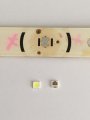
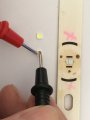
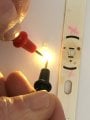
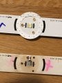
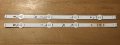
Not sure I am missing something here, I have been renewing some smd LED's on strips rom a TV back light array, have completed 7 , doing the last 2 ( 1 each on separate strips ) , but there seems to be a problem with the polarity , as you can see in the picks , the base of the LED's have 2 surfaces for soldering, a broad surface and a narrow surface, on the back light strip's the broader surface is the +, but the broad contact on the LED is showing positive, when I soldered the first 7 I just soldered broad surface to the positive and tested each one after soldering and each one was ok, but tested these 2 I have left and it wouldn’t light, so ad to remove them both to see why, very, very strange , I don't know what to do now, I can't solder them has per what the polarity is because the contacts will short !.
Help.
Cheers
Spike
Attachments
-
 742.5 KB Views: 23
 -
 1.1 MB Views: 22
 -
 767.3 KB Views: 21

")


