smd led - identifying the cathode

Thread Starter

Mellisa_K

Joined Apr 2, 2017
391

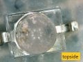
"ZD2005 9061 smd led yel 40mcd gullwing pk10"

The above description is all I have to identify a smd led I bought from jcar australia in an otherwise nondescript packet of ten.

I can't find a datasheet for this ID. The staff at the store couldnt help.

I've found reference to this diode here: http://lab.wildthings.io/2019/02/04/leds-note-to-self/ so I will start with the specs quoted re the current and voltage.

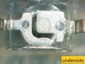
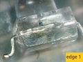
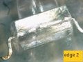
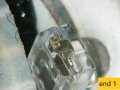
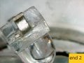
I dont know where the cathode is however. I've included photos for you from each angle. Please see the six thumbnails attached.

I cannot determine a characteristic bevel or depression as per, for example, the picture immediately below.

Can you advise me please.

cathode id on smd led.png
 

Attachments

Last edited by a moderator:

ebeowulf17

Joined Aug 12, 2014
3,307
Hassles like this are one of the reasons to only buy real parts from reputable distributors. If there's no datasheet available, I'm not buying it!

Having said that, you can probably just find your answer with some careful experimentation. LEDs often have relatively low reverse breakdown voltages, so you have to be careful not to reverse bias them at too high a voltage (I've heard that a 5V limit is fairly common, but I don't know if that's true.)

If you get, or make, a low voltage power supply with a current limit that's low enough to protect the diodes, you can simply try both ways and make a note of what works.

I would probably try 2 fresh AA or AAA batteries in series, which will provide 3-3.3V. Then add a 1k resistor in series with that, so your worst case short circuit current is ~3mA and your LED current when oriented properly will be around 1mA.

This should provide enough light output to identify correct orientation, but low enough current and voltage that it won't damage anything unless you leave it hooked up backwards for a long time (and probably not even then.)
 

Thread Starter

Mellisa_K

Joined Apr 2, 2017
391
Hassles like this are one of the reasons to only buy real parts from reputable distributors. If there's no datasheet available, I'm not buying it!

Having said that, you can probably just find your answer with some careful experimentation. LEDs often have relatively low reverse breakdown voltages, so you have to be careful not to reverse bias them at too high a voltage (I've heard that a 5V limit is fairly common, but I don't know if that's true.)

If you get, or make, a low voltage power supply with a current limit that's low enough to protect the diodes, you can simply try both ways and make a note of what works.

I would probably try 2 fresh AA or AAA batteries in series, which will provide 3-3.3V. Then add a 1k resistor in series with that, so your worst case short circuit current is ~3mA and your LED current when oriented properly will be around 1mA.

This should provide enough light output to identify correct orientation, but low enough current and voltage that it won't damage anything unless you leave it hooked up backwards for a long time (and probably not even then.)
great thoughtful reply thanks
Hassles like this are one of the reasons to only buy real parts from reputable distributors. If there's no datasheet available, I'm not buying it!

Having said that, you can probably just find your answer with some careful experimentation. LEDs often have relatively low reverse breakdown voltages, so you have to be careful not to reverse bias them at too high a voltage (I've heard that a 5V limit is fairly common, but I don't know if that's true.)

If you get, or make, a low voltage power supply with a current limit that's low enough to protect the diodes, you can simply try both ways and make a note of what works.

I would probably try 2 fresh AA or AAA batteries in series, which will provide 3-3.3V. Then add a 1k resistor in series with that, so your worst case short circuit current is ~3mA and your LED current when oriented properly will be around 1mA.

This should provide enough light output to identify correct orientation, but low enough current and voltage that it won't damage anything unless you leave it hooked up backwards for a long time (and probably not even then.)
Great thoughtful reply thanks ebeo. I will try this suggestion.

I certainly appreciate your advice about buying components without a datasheet.

Does this configuration underneath give a clue. Im thinking maybe the shape of these "electrodes" might be meaningful.underside led.jpg
 

Thread Starter

Mellisa_K

Joined Apr 2, 2017
391
Hassles like this are one of the reasons to only buy real parts from reputable distributors. If there's no datasheet available, I'm not buying it!

Having said that, you can probably just find your answer with some careful experimentation. LEDs often have relatively low reverse breakdown voltages, so you have to be careful not to reverse bias them at too high a voltage (I've heard that a 5V limit is fairly common, but I don't know if that's true.)

If you get, or make, a low voltage power supply with a current limit that's low enough to protect the diodes, you can simply try both ways and make a note of what works.
EBEOWLF, i did what you said and found the polarity.
here it is. thanks so much.
underside led.jpg
I would probably try 2 fresh AA or AAA batteries in series, which will provide 3-3.3V. Then add a 1k resistor in series with that, so your worst case short circuit current is ~3mA and your LED current when oriented properly will be around 1mA.

This should provide enough light output to identify correct orientation, but low enough current and voltage that it won't damage anything unless you leave it hooked up backwards for a long time (and probably not even then.)
 

jpanhalt

Joined Jan 18, 2008
11,087
The Lumex (
https://www.digikey.com/product-det...nts-inc/SSL-LXA228GC-TR11/67-1385-2-ND/229174 )
appears to be similar. The cathode would be on the left in your topside view or right in the bottom view. That is, the lens is offset toward the cathode. Also, the shape of the electrodes is suggestive of the same assignment.
upload_2019-6-8_5-4-10.png

Since there is little or no standardization. Please let us know what you find to be correct. I am curious.
 

Thread Starter

Mellisa_K

Joined Apr 2, 2017
391
The Lumex (
https://www.digikey.com/product-det...nts-inc/SSL-LXA228GC-TR11/67-1385-2-ND/229174 )
appears to be similar. The cathode would be on the left in your topside view or right in the bottom view. That is, the lens is offset toward the cathode. Also, the shape of the electrodes is suggestive of the same assignment.
View attachment 179304

Since there is little or no standardization. Please let us know what you find to be correct. I am curious.
yes yre correct jpanhalt. this is the answer:underside led.jpg
 

Thread Starter

Mellisa_K

Joined Apr 2, 2017
391
The Lumex (
https://www.digikey.com/product-det...nts-inc/SSL-LXA228GC-TR11/67-1385-2-ND/229174 )
appears to be similar. The cathode would be on the left in your topside view or right in the bottom view. That is, the lens is offset toward the cathode. Also, the shape of the electrodes is suggestive of the same assignment.
View attachment 179304

Since there is little or no standardization. Please let us know what you find to be correct. I am curious.
now pls tell me: how did you arrive at that datasheet? the id no. is nothing like mine, but i'm sure it's the one! many thanks
 

jpanhalt

Joined Jan 18, 2008
11,087
That shape of SMD pins is called "gull wing". So, the DigiKey search went, LED discrete --> more filters --> package case and/or supplier device package --> gull wing . If you add clear/colorless, dome, and so forth you reduce the options to less than 100. Years ago, gull wing pins were very common, e.g., SOIC packages. Now with further reduction in package sizes, they seem to be less common.

The device I arbitrarily chose was listed first. There are other similar devices in the DigiKey table, depending on the search filters used, and another one I checked had the same cathode assignment. The cathode is called the "anvil." It is often larger. The anode is the post. The active emitter is on the cathode in examples I have seen. So, the fact that my tentative assignment had the cathode line up with the center of the lens led me to suggest it.
 

Thread Starter

Mellisa_K

Joined Apr 2, 2017
391
That shape of SMD pins is called "gull wing". So, the DigiKey search went, LED discrete --> more filters -->package case and/or supplier device package --> gull wing . If you add clear/colorless, dome, and so forth you reduce the options to less than 100. Years ago, gull wing pins were very common, e.g., SOIC packages. Now with further reduction in package sizes, they seem to be less common.

The device I arbitrarily chose was listed first. There are other similar devices in the DigiKey table, depending on the search filters used, and another one I checked had the same cathode assignment. The cathode is called the "anvil." It is often larger. The anode is the post. The active emitter is on the cathode in examples I have seen. So, the fact that my tentative assignment had the cathode line up with the center of the lens led me to suggest it.
very good detective work! i get all that. thankyou so much jpan
 

Tonyr1084

Joined Sep 24, 2015
9,744
The reason for this is because the chip - the N region - is mounted on the structure. The P region is on the top of the chip and is attached via a tiny wire. That wire doesn't need to be mounted on a large surface, hence the smaller lead on the left in the picture is the P connection. Hence the anode.
 

SLK001

Joined Nov 29, 2011
1,549
The large square pad (or the base of the chip) is always the cathode.
That's not true. Some chips have the heatsink end on the CATHODE and some have the heatsink end on the ANODE. Repairing the backlights on TVs you always have to determine which is which and obtain the correct part accordingly.

I use my DMM on DIODE mode and just test the LED. If the LED is a 3V model, you will see it dimly light up when the correct polarity is applied. As for datasheets, I have given up on trying to get the correct DS for any LED made in China and 99% of them are made over there. Most of the time, you can't even get the correct part number for the LED - just find the LED that matches the ones you have the closest and go with those. I mostly order by the size of the diode and the heatsink polarity.
 

Tonyr1084

Joined Sep 24, 2015
9,744
That's not true. Some chips have the heatsink end on the CATHODE and some have the heatsink end on the ANODE. Repairing the backlights on TVs you always have to determine which is which and obtain the correct part accordingly.
I stand corrected by the voice of experience.

However, 30 years inspecting electronics, if you have an LED that is poorly, or not marked, you determined the cathode by the larger heatsink. I yield to your experience with LED TV. Since I don't have experience with LED TV's I bow to your experience. Still, with SMT and PTH, it has always been consistent as per the description I've given. Since @Mellisa_K is working with an SMT LED that is either poorly or not marked for polarity, this rule will aid in determining which is which.

I've bought LED's from China that had the cathode marked on the wrong end. With clear LED's you can tell if they're marked correctly or not. Seeing the larger "heatsink" pad you know right away which is the cathode. The negative end. I've inspected many boards that other skilled and experienced inspectors missed the incorrect polarity of LED's and have had to flag them. Not always a popular thing to do since inspectors in general are looked at as being "Bad Work Police". It gets worse when an inspector finds fault with another inspector's work. We all are sensitive to being told our work is faulty.

Anyway, "Generally speaking" the chip LED rests on the larger pad while the connecting spider leg makes contact between the lead and the top of the chip LED. OK, this may not always be the case. But in general, when not working with specialized items such as LED TV Backlights, this rule applies.
 

ebeowulf17

Joined Aug 12, 2014
3,307
I stand corrected by the voice of experience.

However, 30 years inspecting electronics, if you have an LED that is poorly, or not marked, you determined the cathode by the larger heatsink. I yield to your experience with LED TV. Since I don't have experience with LED TV's I bow to your experience. Still, with SMT and PTH, it has always been consistent as per the description I've given. Since @Mellisa_K is working with an SMT LED that is either poorly or not marked for polarity, this rule will aid in determining which is which.

I've bought LED's from China that had the cathode marked on the wrong end. With clear LED's you can tell if they're marked correctly or not. Seeing the larger "heatsink" pad you know right away which is the cathode. The negative end. I've inspected many boards that other skilled and experienced inspectors missed the incorrect polarity of LED's and have had to flag them. Not always a popular thing to do since inspectors in general are looked at as being "Bad Work Police". It gets worse when an inspector finds fault with another inspector's work. We all are sensitive to being told our work is faulty.

Anyway, "Generally speaking" the chip LED rests on the larger pad while the connecting spider leg makes contact between the lead and the top of the chip LED. OK, this may not always be the case. But in general, when not working with specialized items such as LED TV Backlights, this rule applies.
I'll agree that this arrangement is more common, but it's not just specialized items like TV backlights that offer exceptions.

I recently had to redesign one of our control boards which was originally designed by an outside contactor. Somehow we got Gerbers, but no schematic, so I had to be especially careful reverse engineering the original circuit to make sure I understood it before modifying it.

In that process, I found that the silkscreen polarity indication was the opposite of what I expected, so I tried other means of determining its polarity. The datasheet was no help, because the only polarity indication is the length of the leads, which of course get trimmed off after soldering. Then I tried your trick and it seemed to agree with the backwards silkscreen markings that I didn't trust.

Finally, I did physical testing as described above, and also contacted the assembly house. My original circuit analysis had been correct, and the silkscreen markings were wrong, meaning the size-of-the-anvil trick failed too.

And this was nothing special. It was a plain-jane, run of the mill, boring LED. Through hole mounting, red light, clear epoxy, round 5mm base, spec'd at 20mA, very generic:

https://www.ttelectronics.com/TTElectronics/media/ProductFiles/Optoelectronics/Datasheets/OVLL.pdf
 
Top