Slowing Motor

Thread Starter

Jchristie_1979

Joined Jun 29, 2021
15
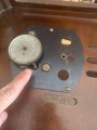
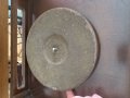
So I need to acquire 704 rpms from motor. If I increase the shaft size of motor by collar or something machined it should keep the rpms at 1666 but reduce ratio thereby reducing output at platter. Correct or way off in left field?
 

Thread Starter

Jchristie_1979

Joined Jun 29, 2021
15
I was off on calculating. It’s a 3/16” shaft thereby creating 3,333 rpm. If calcs are right and placing collar on motor shaft artificially decreases end output than I need a 3/8” collar with 3/16” center hole and a recessed set screw.
 

drc_567

Joined Dec 29, 2008
1,156
... The motor rpm should remain constant. ... 1666 rpm ... and the 2.5" idler wheel turns at 250 rpm, which drives the platter., which turns at 78 rpm. To obtain a reduced platter 33 rpm, you need to reduce the idler to platter diameter ratio by 0.42, so the new idler wheel diameter should be 1.06".
The idler wheel still turns at 250 rpm, but the smaller diameter wheel that is to be fastened to it reduces the platter rpm by 33/78=0.42 ... giving 33 rpm.
 

drc_567

Joined Dec 29, 2008
1,156
... Before you manufacture a new part, get a micrometer and find a piece of pipe or tube about 1.1" dia. that would be easy to cut a thin slice off of it ... maybe 1/2" wide or so. Temporarily glue this section to the idler wheel and verify that the resulting platter rpm is acceptable.
 

Thread Starter

Jchristie_1979

Joined Jun 29, 2021
15
... Before you manufacture a new part, get a micrometer and find a piece of pipe or tube about 1.1" dia. that would be easy to cut a thin slice off of it ... maybe 1/2" wide or so. Temporarily glue this section to the idler wheel and verify that the resulting platter rpm is acceptable.
it’s all in pieces right now. Waiting on new capacitors to come in for radio. The collar should slide on to output shaft of motor which contacts idler wheel
 

Thread Starter

Jchristie_1979

Joined Jun 29, 2021
15
First pic is of motor shaft next to idler wheel. Underside of wheel is on sliding mount with spring tension to hold it against motor shaft and allow for movement. Last pic is of platter. Where I’m pointing to is where rubber of idler wheel contacts platter to spin.
 

Attachments

Tonyr1084

Joined Sep 24, 2015
7,852
Keep in mind that the needle for a 78 rpm record is usually larger than that for a 33 rpm LP. When LP's first came out turntable arms had two needles, one for the "new" LP's and another for the older 78 rpm disks. The user would rotate a selector on the arm to choose which needle was to be used.
THAT's what that was for. I never knew that. And I never had 78's.
It’s a 1942 zenith. Strictly 78’s. Trying to retrofit for 33’s
MORE modern players achieved the variable speeds by the diameter of a collar on the motor shaft. The idler wheel just transferred that power to the platen (record plate). In the diagram below the ratios are arbitrary and only drawn to show a difference in size. A motor spinning at a given RPM will drive the idler wheel fastest on the largest diameter and slowest on the smallest diameter.

One mechanical solution would be to reduce the size of the motor shaft. Using a good metal file with the motor spinning you can reduce the size to some specific number or size to achieve the speed you want. It's a quick and dirty way of achieving your goal. Just understand that if you remove too much shaft material your 33 will spin slower. And at that point there's no going back. So take it in small increments. And perhaps you can either calculate or uncover the correct diameter. If you have another record player with the variable speeds you can simply measure the 33 1/3 shaft size and go from there.

Below The top spindle is for 33 RPM. Middle is for 45 and the bottom for 78's. Since I don't have one of these magical motors I can't just go grab a measurement for you. Sorry.

1625060101461.png
 

Thread Starter

Jchristie_1979

Joined Jun 29, 2021
15
THAT's what that was for. I never knew that. And I never had 78's.

MORE modern players achieved the variable speeds by the diameter of a collar on the motor shaft. The idler wheel just transferred that power to the platen (record plate). In the diagram below the ratios are arbitrary and only drawn to show a difference in size. A motor spinning at a given RPM will drive the idler wheel fastest on the largest diameter and slowest on the smallest diameter.

One mechanical solution would be to reduce the size of the motor shaft. Using a good metal file with the motor spinning you can reduce the size to some specific number or size to achieve the speed you want. It's a quick and dirty way of achieving your goal. Just understand that if you remove too much shaft material your 33 will spin slower. And at that point there's no going back. So take it in small increments. And perhaps you can either calculate or uncover the correct diameter. If you have another record player with the variable speeds you can simply measure the 33 1/3 shaft size and go from there.

Below The top spindle is for 33 RPM. Middle is for 45 and the bottom for 78's. Since I don't have one of these magical motors I can't just go grab a measurement for you. Sorry.

View attachment 242486
Thank you so much. I figured that out last night when I tried to prototype it. Going down it would need a 1/10” shaft. Not sure I’m comfortable with that thin a shaft
 

shortbus

Joined Sep 30, 2009
10,045
Thank you so much. I figured that out last night when I tried to prototype it. Going down it would need a 1/10” shaft. Not sure I’m comfortable with that thin a shaft
Why? There are many many of them out there being used in things taking more power/torque than a turntable. Most small high power DC motors are less than that diameter. Just don't try to do it with a file, it need turned in a lathe to end up being round.
 
Top