SLA Backup Battery Charger Recommendation

Thread Starter

ischonfeld

Joined Jun 22, 2019
63
Still working on the alarm system replacement for my 1980's era Napco Magnum 850 panel. Now looking at the power supply end of things and in particular, the battery backup. The system runs on 12VDC, and the main (external) power supply I have is 16VDC, regulated. I'm using a Recom DC-DC switching converter to get from 16V to 12V instead of using something like a linear regulator. It's more efficient than a linear regulator and can handle the current. Under normal conditions, current draw is well under 1A, but under alarm conditions it can go to 2.5A or more depending on how many heads go off.

For a battery backup, I'm using a 12V 7Ah SLA battery, which is normally isolated from the system (at least for current drawn from the battery) by a relay.

My concern is that for 99.99% of the time, the battery is not being used but needs to be maintained in a ready state. But I don't want to damage the battery by leaving on charge for months/years at a time.

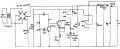
I found this circuit but I'm not entirely happy with it. On the "pro" side, it appears to only kick in when (a) there is utility power, and (b) when the battery charge level is below a set threshold. On the "con" side, (a) it doesn't do a trickle charge and (b) appears to drain the battery all the time through 11K resistors once the charge threshold is reached. And it will cycle on and off due to that. I can probably do a little redesign to eliminate the constant battery drain, but still not ideal.

Also, with 16V DC as input, I'd need to add resistance (and do a little re-routing) to the charging side to limit the current into the battery when charging.

Battery Backup Circuit.jpg

I've searched the forums but haven't come up with something fairly simple that maintains the battery charge but a the same time protects it from being on charge long term.

Any recommendations would be appreciated.

Thanks.
 

Attachments

Thread Starter

ischonfeld

Joined Jun 22, 2019
63
Go to your local Walmart, or Auto-Parts-Store, and buy a "Battery-Maintainer",
it beats regularly replacing your Battery.
I'm trying to stay away from that kind of solution. I don't have (or want) 120V in the alarm system enclosure and don't really want another thing to plug in - even though that means building a circuit to do the same thing.
 

LowQCab

Joined Nov 6, 2012
5,101
The built-in Power-Supply-Transformer in your Alarm is very small at only ~14-Watts.
This may be just fine after everything settles-down and the Battery is completely charged,
but it worries me as far as, I wouldn't cut the specifications so close if I were to design it.

Just replace the "LapTop-Power-Supply" Brick in my supplied Schematic,
with your already existing ~16-Volt Power-Supply.

If the Alarm-System is in an environment that is 24/7 Temperature-Controlled,
a much simpler Schematic can be provided.
If it is not in a Temperature-Controlled-Environment,
the Charger MUST have Temperature-Compensation.


Please provide a full Schematic of the Alarm-System.
Just stating "16-Volts" is not enough information.
.
.
.
 

MrChips

Joined Oct 2, 2009
34,628
I have had many 12V 7Ah SLABs destroyed by the device manufacturer’s automatic chargers that failed to turn off after the battery was fully charged. Now I don’t rely on their chargers and simply try to remember to turn off a bench PSU used as the charger.
 

Thread Starter

ischonfeld

Joined Jun 22, 2019
63
The built-in Power-Supply-Transformer in your Alarm is very small at only ~14-Watts.
This may be just fine after everything settles-down and the Battery is completely charged,
but it worries me as far as, I wouldn't cut the specifications so close if I were to design it.

Just replace the "LapTop-Power-Supply" Brick in my supplied Schematic,
with your already existing ~16-Volt Power-Supply.

If the Alarm-System is in an environment that is 24/7 Temperature-Controlled,
a much simpler Schematic can be provided.
If it is not in a Temperature-Controlled-Environment,
the Charger MUST have Temperature-Compensation.


Please provide a full Schematic of the Alarm-System.
Just stating "16-Volts" is not enough information.
The existing power supply transformer is much larger than that but I'm not using it for my new panel. As it turns out, 14W wouldn't even be enough power for the old panel once it goes into alarm and has to supply the main circuit board, wired smoke detectors and the speaker.

The new power supply is something I already have and have tested. It is a 16V, 4A, switching supply, well regulated (tested under various loads and for ripple voltage).

After the system switches to battery power and the battery needs to be recharged, I would expect to limit the charging current to much less than 3A even though the battery could certainly tolerate it. Yes, it would mean several hours to bring it back up to full charge.

The panel is in a temperature controlled environment.

I will try to post a schematic - perhaps only the relevant portion since there's a lot going on between the main controller, zone sensing, LCD keypads, internet interface, etc. Each of these functions is handled by separate microcontrollers (MKR1000, ESP32) with an RS485 interface between the main panel and each LCD keypad (3). My idea is that the "core" (zone sensing, alarm and siren) of the panel will continue to operate even if one or more of the other pieces doesn't. And I can add functionality later such as Matter/Alexa interface by adding pieces to the RS485 bus.

Question: Once your circuit reaches the setpoint voltage, does it shut off entirely, continue to supply a small trickle charge, or something else? And what would be the recommended "full charge" cutoff voltage for a typical SLA 12V battery?

Thanks!
 

Thread Starter

ischonfeld

Joined Jun 22, 2019
63
I have had many 12V 7Ah SLABs destroyed by the device manufacturer’s automatic chargers that failed to turn off after the battery was fully charged. Now I don’t rely on their chargers and simply try to remember to turn off a bench PSU used as the charger.
I've been pretty lucky with Napco's 1980's vintage automatic charger which is part of their panel. When I replace the panel's 12V SLA battery every 3-5 years, it still has plenty of life left (unlike some UPS batteries I've had to replace that were clearly damaged by their charging circuit in the same timeframe).

A bench charger isn't a bad idea but I know I won't remember to charge periodically and I can't expect my wife to try to do it.
 

crutschow

Joined Mar 14, 2008
38,316
Below is the LTspice sim of an example 12V lead-acid battery charger using an LDO regulator, that charges at a constant-current until the battery is charged, and then drops to a trickle-charge voltage:
The charging voltage (here about 14.4V) is determined by the values of R1 and R2.
When the trickle charge current is reached (here about 170mA) as determined by the difference between V(Bias) and V(Lim), the U3 output goes low, dropping the voltage to the trickle-charge value (here 13.7v) as determined by R1||R12 and R2.
This also turns on LED D2 to indicate charging is complete.

If the battery voltage drops below the trickle-charge voltage, the charger will revert to the charging mode (here shown at the 26s point), until it is again at the charging voltage.

U4 can dissipate several watts of power, so needs to be a TO-220 type case mounted on a heatsink.

Note that this has not be built and tested so may require some tweaking of the real circuit resistor values to get the voltages and currents you want.

EDIT: Added C3 to smooth transition from CV charging to trickle-charge

1733454983601.png
 
Last edited:

Thread Starter

ischonfeld

Joined Jun 22, 2019
63
Below is the LTspice sim of an example 12V lead-acid battery charger using an LDO regulator, that charges at a constant-current until the battery is charged, and then drops to a trickle-charge voltage:
Thank you. I saw your original circuit: LM317 12V Lead-Acid Battery Charger With 3-Step Auto CC/CV and Trickle-Charge on electro-tech-online.com and was planning on using it unless something else came up. I would be using a LM1117 in the original circuit due to only having 16VDC to work with. Your above circuit is very similar.

Any advantage of one vs the other?

Thanks again - you have been an immense help.
 

LowQCab

Joined Nov 6, 2012
5,101
There can be quite a bit of confusion surrounding the charging of Lead-Acid-Batteries,
a verbal description may have You believing that the Circuit has all sorts of
mysterious automatic or timed functions.
None of this "complexity" is necessary.

The most important Charger feature is that the VOLTAGE must correspond
to the "Core-Temperature" or "average-temperature" of the Battery..

The Current-Limiting feature is strictly to prevent Battery-Overheating
but the Current-Limiting may also protect the Charger Circuitry / Power-Supply, from possible damage.
Current-Limiting is determined by the Battery manufacturer,
and/or,
generally, by the physical size of the Battery, and it's various Current-Output-Ratings.

Generally speaking, the Battery will last longer at "Room-Temperature" or cooler.

The Schematic that I posted earlier contains
a graph depicting the ideal Charging-Voltage vs Battery-Temperature.

.
=============================================================
Charging for Cycle Operation

Cyclic applications generally require that the
recharging be done in a relatively short time.

The initial charge current, however, must not exceed
0.30 x C amps, (for small Sealed Lead-Acid Batteries).

Just as battery voltage drops during discharge,
it slowly rises during charge.

Full charge is determined by voltage and inflowing current.

When, at a charge voltage of 2.45 volts/cell, (14.7V),
the current accepted by the battery drops to less than
0.01 x C amps (1% of rated capacity), the battery is fully charged,
and the charger should be disconnected,
or switched to a float voltage of 2.25 to 2.30 volts/cell, (13.8V).

The voltage should not be allowed to rise above 2.45 volts/cell, (14.7).
---------------------------------------------------------------------------------------

Charging for Standby Operation

Standby applications generally do not require that the
battery be charged as fast or as frequently as in cycle operation.

However, the battery must be kept constantly charged to replace the energy
that is expended due to internal loss, and deterioration of the battery.

Although these losses are very low in Power-Sonic batteries,
they must be replaced at the rate the battery self discharges;
but at the same time,
the battery must not be given more than these losses or it will be overcharged.

To accomplish this,
a constant voltage method of charging called “float charging” is used.

The recommended constant float voltage is 2.30 volts per cell, (13.8V).

Maintaining this float voltage will allow the battery to define its own
current level, and remain fully charged,
without having to disconnect the charger from the battery.

The trickle current for a fully charged battery,
floating at the recommended charge voltage,
will typically hover around the O.OO1C rate,
(10mA for a 10AH battery, for example).

The float charger is basically a constant voltage power supply.

As in cycle chargers, care must be exercised not to exceed
the initial charge current of 0.30 x C amperes.
==========================================================
.
.
.
Lead-Acid Temp Graph .png.
Temp Compensation .PNG.
.
.
 

MisterBill2

Joined Jan 23, 2018
27,164
I suggest using a charger that delivers the minimum FLOAT VOLTAGE, and verifying that is what it is doing a few times. It is not likely that a fast recharge will ever be needed in the event of a long alarm "announcement" period.
 
Top