Simpler alternative to 555 - am I right?

Thread Starter

greg123

Joined Mar 23, 2008
13
Hi guys,

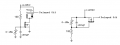
I have been making a 555 timer to act as a 'delay on break' eg when the 12v trigger is cut the output is fired to provide 12v for a period of very roughly 0-60 seconds, adjustable. It will be powered by 12v car supply, so un-smooth 12-15v dc. The 'trigger' or 'switched' line is also car 12v, from a switch in the car. I need the output to stay switched on for a while after I switch the switch off and I think this circuit may do it easier and smaller than a 555. Am I right?

FYI the load on the output is about 2a (5a would be better) at 12v from a solonoid coil. It will need a 'hard' off, eg it needs full supply voltage to operate and when switched off it can't 'ramp' down it has to have the suply cut, or a gradually lowering voltage could hold the solonoid open an unpredictable amount of time.

Please see attached and give comment, also on the choice of transistor as I don't know, and if or not I need to have the transisotr switching a relay or if I can use some sort of power transistor.

Thanks, Greg.
 

Attachments

Thread Starter

greg123

Joined Mar 23, 2008
13
PS sorry if I wired the tranny the wrong way, also my 1st attempt at using the circuit drawing software which I coulnd't even find a symbol for a switch in and took me ages!!!
 

bloguetronica

Joined Apr 27, 2007
1,541
I don't know it using a MOSFET is a good idea. They are static sensitive, and even with a protection diode, they may get damaged by the relay's back EMF.

I suggest you to use a TIP42 PNP bipolar transistor (or a TIP32 if you don't want to use a safety factor of 2) to drive the relay and a protection diode parallel to the relay coil. You can use a 1N4001 for that.
 

Wendy

Joined Mar 24, 2008
23,415
There are indeed a lot of alternatives to the 555. I have to agree a bipolar transistor is a lot more rugged for this application, but an MOSFET would work. The capacitor should be on the gate, and the relay (with diode protection) on the source. When I'm not nodding off so hard I'll try redrawing your concept to see if it what you want.
 

Thread Starter

greg123

Joined Mar 23, 2008
13
Hi guys,

Thanks very much for the comments. I purely picked a MOFSET due to I read they have low internal leakage so better for the timing cap, but I have no practical experience so more than happy to swap caps! Bill if you could re-draw that would be fantastic. I was hoping to avoid a relay if poss, do you think a power capacitor of any kind that would handle up to 5a 15v would do? Or am I just better off going the relay route?

Regards, Greg.
 

Wendy

Joined Mar 24, 2008
23,415
OK, sorry about the time it took, got busy with other stuff. I have never built this circuit, but I have seen a variation used in a cheap DVM to turn it off automatically in 10 minutes or so. I've cleaned it up, but if someone sees something I missed please let me know.


Thread Starter

greg123

Joined Mar 23, 2008
13
Thanks Bill. I like the idea of transistor only, can I have the same sort of clean on or off output and if so what sort of transistor would I need to handle 5 or 10a? Is there any reason to go the relay route? I'd like to keep componant count small as this is part of a bigger circuit.

Greg.
 

jpanhalt

Joined Jan 18, 2008
11,087
I've used variations of the circuit on the left. Are there any problems with getting sufficient gate drive for the circuit on the right?

John
 

Ron H

Joined Apr 14, 2005
7,063
OK, sorry about the time it took, got busy with other stuff. I have never built this circuit, but I have seen a variation used in a cheap DVM to turn it off automatically in 10 minutes or so. I've cleaned it up, but if someone sees something I missed please let me know.

I don't understand where the delayed power comes from. Don't you need a switch in place of the 1N4454?
The circuit on the right is a source follower, and will suffer several volts drop across the FET. You could use a PMOS, as below.

I would pay attention about the transistor's instantaneous power dissipation when the circuit on the right is turning off. It is relatively high for several seconds, reaching a peak of 18W for a 2 ohm load.
 

Attachments

Wendy

Joined Mar 24, 2008
23,415
Doh! I think I've just been incredibly stupid. Comes from free handing after I get off work at 7:00AM in the morning. A switch in place of the diode would do it, at lease for the delay. I screwed this one up so bad I don't think I'll redraw the schematic.

The idea of the FET getting hot or burning out during discharge is valid. The relay would force the circuit to be either on/off, and the second schematic I whipped out in my fog because I read he was trying to get rid of the relay.

This is how the magic blue smoke escapes folks.

Greg, I apologize, for what it is worth.
 

Ron H

Joined Apr 14, 2005
7,063
With three more parts, you can add hysteresis (see attached), reducing the dissipation during switching, but the returns are diminishing. A 555 might be a better solution, seeing as how the delay is more predictable.
The new circuit also has a little residual current into the load during the off time, which could be bad. The size of the base drive resistor is a tradeoff between switching time and residual load current.
 

Attachments

Thread Starter

greg123

Joined Mar 23, 2008
13
Well no apologies needed I'd like to thank everyone for help so far! I have noticed a couple of things,

1) switches seem to be to earth, I need it with a switched +12v.
2) the delay on break needs to be clean. It can't have residual voltage when 'off' or less than supply voltage when being fed. The output of a relay suits this perfectly but I wanted to keep the circuit simple and presumed there was a transistor which would do a similar sort of output?
3) current or voltage into load after the delay time is up would be bad.

Not sure if that helps at all, I thought I was on to something a bit simpler than a 555 but now I'm not sure.... Delay on break isn't exactly rocket science so I'm sure I'm missing something here!

Greg.
 

jpanhalt

Joined Jan 18, 2008
11,087
This was just put in another thread:

http://forum.allaboutcircuits.com/attachment.php?attachmentid=2634&d=1207068519

The switch (labeled "control') is to +12V. When switch is closed, relay pulls in. You can use either the N.O. or N.C. contacts, depending on how you want the load to respond. When switch is open, relays stays closed for a short period depending on the RC constant. John

Edit: Just noticed that circuit has a "decoupler". Ignore that, and put a small capacitor (about 1 nF) directly across the diode, if needed.
 

Wendy

Joined Mar 24, 2008
23,415
You could disconnect the diode from the 12V and treat it as a relatively high power input. This I will redraw, but I'll leave my old schematic up as a lesson in humility. The second circuit will also switch, kind of, but it will still go though a long analogue phase where it could heat up.


I know I said I wasn't going to do this. I'm so weak. :D
 

Ron H

Joined Apr 14, 2005
7,063
You could disconnect the diode from the 12V and treat it as a relatively high power input. This I will redraw, but I'll leave my old schematic up as a lesson in humility. The second circuit will also switch, kind of, but it will still go though a long analogue phase where it could heat up.

Bill, you may have missed my comment about the circuit on the right being a source follower. The transistor will have several volts dropped across it.
The switch should have a resistor in series (100 ohms or so) to limit the current when the capacitor is charging. Otherwise the switch contact life may be shortened. You also need a resistor in series with the 1Meg pot, for obvious reasons.
 

Wendy

Joined Mar 24, 2008
23,415
Most switches can handle something like a 100 uf capacitor charging, they tend to be way overrated for the job. That is one issue I wouldn't worry too much about, otherwise power supplies and other circuits with bybass caps the world over would be in trouble. The diode can be boosted to a 1N4001 to make sure it has the capacity. The heating of the FET is a serious issue, I'm not as familiar with MOSFETs as I would like, but that is another thread I will eventually get around to posting. When you refer to a source follower, are you saying the 4th circuit will act like an emitter follower on a bipolar design? That part of the ebook isn't finished, and I do need to study it further.

Parts count on these designs is important, it is one of the stated design goals of the project. There is a fine line between whether a part is actually needed, or is added just in case, many cases it comes down to a judgment call.

As near as I can tell, I'm the only one using this display technique on this forum, which has a lot of advantages from what I can see. I use a photobucket link, which includes the [ URL] (I deliberately added a space in the brackets to keep the forum software from freaking out). The .gif files work much better than the .jpg versions, and being stored offline adds nothing to the memory use on this forum.
 

Ron H

Joined Apr 14, 2005
7,063
Bill, the gate voltage needs to be about 10V above the source for the NMOS to be fully on (5V for logic FETs). If you are familiar with NMOS pullups on H-bridges, your circuit has the same problem. H-bridges generally use a bootstrap capacitor, but you have no signal available to do it that way.
 

jpanhalt

Joined Jan 18, 2008
11,087
My concern, as expressed earlier, is that the circuits on the right side are effectively high-side N-channel mosfet switches. As such, as soon as the gate turns on, the voltage drop across the mosfet drops to almost nothing (assuming the relay draws less than a few amps). That makes Vgs too low to keep the fet turned fully on, which will lead also to overheating.

Have you seen that circuit in operation and how is that potential problem addressed? John
 

Ron H

Joined Apr 14, 2005
7,063
My concern, as expressed earlier, is that the circuits on the right side are effectively high-side N-channel mosfet switches. As such, as soon as the gate turns on, the voltage drop across the mosfet drops to almost nothing (assuming the relay draws less than a few amps). That makes Vgs too low to keep the fet turned fully on, which will lead also to overheating.

Have you seen that circuit in operation and how is that potential problem addressed? John
John, I agree with your conclusion about overheating (the same point I have been making - the transistor is a source follower), but I don't understand what this means:
As such, as soon as the gate turns on, the voltage drop across the mosfet drops to almost nothing
:confused:
Zero voltage drop equates to zero power.:eek:
 

jpanhalt

Joined Jan 18, 2008
11,087
What I mean is with an RDSon of less than an ohm and a current of, say, 1 amp, the voltage drop across the mosfet will be less than 1V. That means, the Vgs (if the gate is tied to Vcc) will also be less than a volt. At least that is the way it is explained in the IR literature.

I think we are saying the same thing, namely that Vgs need to be 10V for regular mosfets. If you notice the times on our posts, I was writing while you were posting. I don't think mine adds anything to your post, except introduction of the term Vds. John

Edits: I mean Vgs not Vds
Edit#2: BTW, I notice the OP wants something on the order of a 60 second delay. The left circuit works fine for a few hundred ms, but would keep the mosfet in the linear region for a relatively long time , if one had it set for a 60 second delay. For such long delays, I would consider something like a comparator between the switching transistor and the RC timer to give a rapid turn-on/turn-off period.
 
Top