Simple water level logic cuircuit. HELP!

Thread Starter

alexchala

Joined Feb 8, 2018
16
Hi guys first post at to be honest ive been stuck on this one for hours now.

The question goes

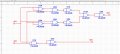
Two water tanks each have a sensor indicating whether the tank is empty. Build a logic cirucit using gates to turn on a yellow light when one water tank is empty and a red light when both tanks are empty. The yellow light should be off when both tanks are empty.

I have a and gate for the two tank inputs to indicate the red light output and a or gate to indicate the yellow light. but i cannot figure out how to get the or gate output to turn off when the and gate comes on for the red light.

Guidence please. i know its something super simple that im just not seeing!
 

Thread Starter

alexchala

Joined Feb 8, 2018
16
Cheers mate. Have done so and it worked. Now ive been asked to create the same log using only NOR and NAND gates and am stuck again.

I have got the red LED controll fine as i just put the two tank intputs into a NAND gate and then the NAND gate output into both INPUTs of a 2 input NOR gate. again this works fine although i am now stuck of the yellow light again.
 

ericgibbs

Joined Jan 29, 2010
18,848
hi alex,
Is this a homework assignment, if Yes, I will move it to the Homework Forum.
E
MOD: moved to homework.
 
Last edited:

LesJones

Joined Jan 8, 2017
4,189
This now sounds like homework so I will not tell you HOW to do it. For homework we try to give you tips to point you in the right direction. Have you drawn a truth table for the yellow LED ? One thing you have to consider is do the tanks empty in a particular sequence or can it be either one that is empty first ?

Les.
 
Last edited:

MrAl

Joined Jun 17, 2014
11,472
Cheers mate. Have done so and it worked. Now ive been asked to create the same log using only NOR and NAND gates and am stuck again.

I have got the red LED controll fine as i just put the two tank intputs into a NAND gate and then the NAND gate output into both INPUTs of a 2 input NOR gate. again this works fine although i am now stuck of the yellow light again.
Hi,

Look up negative and positive logic.
For example, a positive logic AND gate is a negative logic OR gate, and a negative logic AND gate is a positive logic OR gate. You transform from one to the other by inverting all inputs and outputs and logical connectives conceptually, but if you actually do invert all inputs and outputs physically then you actually change the logic function entirely from one to the other.

To give a simple example, a positive logic AND gate produces a 1 output when BOTH inputs are 1. The implication here though is that it produces a 0 output whenever ONE input is 0, which is simply a negative logic OR gate. So we went from positive logic AND to negative logic OR by simply looking at the data differently.
If you actually invert the inputs and outputs of the AND gate physically however (with inverters), then you get a positive logic OR gate because then a 1 on either inverter input produces a 0 on either input of the AND gate, and that produces a 0 on the output and inverted that is 1, so overall a 1 on either input produces a 1 on the output. So when we actually invert all inputs and outputs we transform from AND to OR for the positive logic AND gate.
Also, if you have either a NAND gate or NOR gate, if you tie the two inputs together you create an inverter.

See if those hints help.
 
Last edited:

Thread Starter

alexchala

Joined Feb 8, 2018
16
OK, so managed to get the logic done ONLY using NOR and NAND gates, the Boolean algebra of the NAND and NOR gate logic on my completed circuit when manipulated simplifies down the the exact same logic used to complete the first scenario using an xor and and gate. which was (AB')+(A'B) for the yellow light and (AB) for the red light.

I attached an image of what i came up with only using NAND and NOR gates. Could the same task be done using less NAND and NOR gates only or have got it in simplest form?

Also how do you guys go about designing these sorts of logic problems? Do you drawn truth tables for the output requirements and then look for gates accordingly? is there a systematic approach that always works?

(The image of NAND an NOR logic is attatched)
 

Attachments

Thread Starter

alexchala

Joined Feb 8, 2018
16
Just realized that there are 2 different Types of negative logic NAND and NOR gates depending on whether the bubble is on the input or output side will create different NAND or NOR gates of different logic but they still only equal 2 different logic truth tables, either NAND or NOR
 

MrAl

Joined Jun 17, 2014
11,472
OK, so managed to get the logic done ONLY using NOR and NAND gates, the Boolean algebra of the NAND and NOR gate logic on my completed circuit when manipulated simplifies down the the exact same logic used to complete the first scenario using an xor and and gate. which was (AB')+(A'B) for the yellow light and (AB) for the red light.

I attached an image of what i came up with only using NAND and NOR gates. Could the same task be done using less NAND and NOR gates only or have got it in simplest form?

Also how do you guys go about designing these sorts of logic problems? Do you drawn truth tables for the output requirements and then look for gates accordingly? is there a systematic approach that always works?

(The image of NAND an NOR logic is attatched)
A question about your sensors:
Do they output a logic high or logic low when the tank is empty?
 
Top