simple water level Indicator

Thread Starter

abhimanyu143

Joined Aug 25, 2014
211
Hello everybody
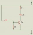
I am trying to make simple water level Indicator using some transistors.I want to do on breadboard. I made circuit diagram
I tried to run on proteus software. but Its not working

whats wrong with circuit ?
 

Attachments

MikeML

Joined Oct 2, 2009
5,444
Do you really believe that the sensor has an effective resistance of zero when submerged? That is the way you modelled it. If so, why does the transistor not vaporize? What limits the base current?

The bigger question, what is the conductivity (1/resistance) of metallic electrodes when submerged in distilled water? tap water? sea water?

What metal do you use for the electrodes?

What is the long term effect of passing a DC current between two submerged metallic electrodes?
 
Last edited:

DickCappels

Joined Aug 21, 2008
10,180
Please put a resistor in series with the base in both your simulation and your breadboard to limit the current to a few milliamps.

What do you expect to see in the simulator when the circuit is "working"? (In other words, how do you know it is not working?)

If your LED is a white or blue LED you are leaving precious little voltage for the LED series resistor to develop current. Try dooubling the voltage and see if current starts flowing through the resistor.
 

ErnieM

Joined Apr 24, 2011
8,377
I have done similar things using CMOS gates but a single MOSFET should also work.

You need a lower value for R1 (300 to 500 ohms) and much higher for R2 (100k to 10 Meg's). Neither value is very critical.

This circuit may never simulate correctly, better to build it and play with some values.
 

DickCappels

Joined Aug 21, 2008
10,180
Towards EarnieM's comments, In the real-world circuit your transistor might have too little current gain to be able to deliver appreciable current to the LED. MOSFETs (properly protected) would be much better for this sort of application.
 

MrCarlos

Joined Jan 2, 2010
400
Hello abhimanyu143

Not all devices have in their libraries That ISIS Proteus, are working properly.
Unfortunately you have selected the LED and transistor that do not working properly.

Now, your original question: whats Wrong With circuit?
Because the devices that you select does not work properly in the simulator.
But. . .Probably if you make the circuit in reality it works.

It is very difficult to make a water level indicator with only the devices that We see in the image you enclose In your original message.
Let me make a couple of assumptions:
When the electrodes are covered with water, the LED should light.
The transistor will work as a switch, saturation and cut.
From the foregoing we need to know the electrical characteristics of the water and the transistor. . . Right?
A- What are the electrical characteristics of the LED: VF: IF: ??
B- How many ohms per area has the water where electrodes will be ??
C- What is the value of the parameter: VCE (sat) @ CI LED of the transistor that you use ??
D- What current IB requires the transistor to be saturated ??
Data sheets for the LED and transistor You are going to use could be down load from this link: http://www.alldatasheet.com/

Take a look at the file: LED's In ISIS Proteus.DSN (Ver 7.8) contained on the .ZIP file.
Changing the switch you will notice that some sets Transistor-LED work well.
While others do not work well.
If you have an older version that I mention you can assembly, the circuit, based on the image shown in the .PDF document that I attached.
And if you have a later version 7.8 you can import the file contained in the .ZIP file.
Note: The value of the resistors in the design were selected arbitrarily.
I also agree that better would be your design with MOSFET transistors rather than bipolar.

I hope I helped you.
 

Attachments

Top