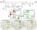
Simple Switching Regulator

Thread Starter

Wendy

Joined Mar 24, 2008
23,429
Sharpie is quick and easy. I bought and use a laser printer for the latter method, matter of fact from the same website you show. I still need to get some decent software and learn how to use it. I've some inqueries on usenet for just that process.
 

SgtWookie

Joined Jul 17, 2007
22,230
Have you looked at Cadsoft's Eagle Layout Editor?
They have a freeware version that's limited as far as layers (2), size of the board (roughly 3"x4") and 1 page per schematic, but you can still do quite a bit with it.

http://www.cadsoftusa.com/
It takes a good bit of getting used to, but it's pretty powerful.

Unfortunately, the freeware version doesn't have built-in SPICE emulation, or I'm sure it would get a lot more attention.

I fiddled around with ExpressPCB a bit, but I didn't find it suitable for home-made PCB's as there is no option to reverse a print image. I also found their choice of colors for the PCB editor very hard to look at, and found no way to reconfigure them. But if you want a tool that will make you dependent on a specific PCB vendor, be my guest ;)
 

Thread Starter

Wendy

Joined Mar 24, 2008
23,429
What I really need is a graphic package that will print out real size and vector style graphics on a laser printer. I've used paint to make PCBs, it almost works. The main problem with Eaglesoft I haven't figured out is how to handle components that aren't in the library, since I use surplus stuff a lot of the time the odd of this happening is quite high. But this is a subject I'll be bringing up in another thread eventually.
 

jpanhalt

Joined Jan 18, 2008
11,087
Re: Eagle library

Just pick something with the right package. It doesn't really matter very often* what the symbol or device is. Attach to whatever pins you want to use. If the name of the device bothers you, use the change name/value button(s) to change it. You may get an error saying there is no user defined value associated with the part. Click though that and enter whatever you want. John

*When there is a problem, it is usually with the power/ground pins. Just pick something with the right power connections. Once you get used to the interface, changing more aspects of the device will seem much more logical, at least to some people.
 

Søren

Joined Sep 2, 2006
472
Hi,

I don't like that 'black regulator' link... I don't buy the 93.1% efficiency..
Well, it should be a short matter to build one and give it a test drive to get some hard facts on it rather than just assuming. It's so easy to critisice something you haven't experienced, but not much harder to get knowledge :)

Besides, even with half the efficiency, it would be far better than a linear and you get both a really small size and the option to get into the function of each component - and modify each parameter should you want it.
 

Thread Starter

Wendy

Joined Mar 24, 2008
23,429
I like it, though I'm still working out what keeps it from ever being linear. One thing about the base schematic though, it is minor, is that if I read this correctly it HAS to have a load. A simple LED/resistor would do it though. I'm deep enough into my design I'm going to try finishing it, but the other looks interesting. I assume the parts list is the same as the other circuit he refers to.

His design has all the same drawbacks mine does, a fuse and a load is a must, along with a simple crowbar circuit in the form of a high wattage zener. I may redraw it as I interprete it and post it here. Does this run into copywrite issues?
 

Attachments

Last edited:

SgtWookie

Joined Jul 17, 2007
22,230
I may redraw it as I interprete it and post it here. Does this run into copyright issues?
If you completely re-draw the schematic, I don't see how?

But the copyright laws read (sic) that at least 50% of a copyright-protected piece must be changed for it to be a new work.

An implicit copyright for an original work is good for 75 years. Unless the original copyright holder has gone to the trouble of filing for a copyright, registering their work, and other legal-type things, the implicit copyright is rather difficult to get enforced.
 

jpanhalt

Joined Jan 18, 2008
11,087
Let me add that copyright covers the form and to some extent the content of a piece of work. It does not cover information, e.g., facts. For example, you can write a biography. The facts are not copyrighted, but the words used and the order in which they are written (i.e., the form) is copyrighted. It seems to me the problem with a schematic is deciding what part is information and what part is form. Are the specific connections information or form? Is it the netlist that is copyrighted or the way the connections are shown? I don't know.

Nevertheless, in the US, you would still have to prove damages for infringement, which can be extremely hard to do. Hence, what usually happens is the infringer gets a letter telling him to stop infringing, and he does. It is an interesting circuit, and quite honestly, I would like to know whether it works too.

John
 

thingmaker3

Joined May 16, 2005
5,083
http://www.copyright.gov/circs/circ1.html#wwp ...so schematics would be "illustrations" and netlists would not be protected. Netlists might be protected by patent, of course.


See also the notes on "fair use doctrine:" http://www.copyright.gov/fls/fl102.html

All About Circuits promotes itself as an educational site, and Bill's project (as declared on the first page) is certainly not commercial in nature.

Shooting off an eMail to ask for permission would be a simple precaution.
 

Thread Starter

Wendy

Joined Mar 24, 2008
23,429
OK, I'm back to this project, with some changes. Here is my latest brainstorm:


Switching Regulator Parts List
U1 – 1458 dual op amp (or better)
VR1 – 10V zener diode, 5W
VR2, 3 – 3mm Red LEDs
VR4 – 10V zener diode, 1W
Q1 – MPS2955 PNP power transistor
Q2 – 2N2222 NPN transistor
D1 – Red LED
D2 – Green LED
CR4 – 1N4001
R1, 11 – 1 K
Ω ¼W resistor
R2 – 2K
Ω Variable resistor
R3, 4, 5, 6, 7 – 10KΩ ¼W resistor
R8 – 4.
7KΩ ¼W resistor
R9 – 150
Ω 1W resistor
R10 – 360Ω ¼W
C1, 2 – 470µF 35V Capacitor
L1 – 350µH

It's grown a bit, but not as much as you would think. I plan on building it pretty soon, have all the parts (parts list pending).

This version is for a Asus laptop that blew out. I'll be testing it pretty thoughly before using it, you betcha.
 

Attachments

Last edited:

ronv

Joined Nov 12, 2008
3,770
Bill,
I built a similar circuit for a step down for my golf cart battery gage. The only difference was I had to use a transistor where you have the second comparitor because I was using 48 volts. Has a little ripple, but cool as a cucumber.:)
 

Thread Starter

Wendy

Joined Mar 24, 2008
23,429
Well, the son of a gun didn't work on several levels. CR4 was wrong, I had to turn it around. The initial Schmitt Trigger design was too wide, so of course I went the other extreme and went to 1KΩ for R4. I think this is why it doesn't work correctly yet, it seems to be in an analog mode, some switching is happening, but overall the design seems to be operating in the analog region.

The reason I say this is I'm getting the same current in as the current out, so no conversion is taking place, and Q1 is getting pretty hot. This is with 14.8VDC in at 2.1A. In spite of this I'm getting excellent regulation. I'm using a JRC4565 op amp, a much better op amp than the 1458.

My next step is to widen the Schmitt Trigger to as wide as it can go. I'll let you know how it works.
{img]https://forum.allaboutcircuits.com/threads/simple-switching-regulator.10339/page-2[/img]https://forum.allaboutcircuits.com/attachments/switching-regulator-2-png.8581/[/img]


Switching Regulator Parts List
U1 – JRC4565 (1458 style dual op amp w/ better specs)
VR1 – 10V zener diode, 5W
VR2, 3 – 3mm Red LEDs
VR4 – 10V zener diode, 1W
Q1 – MPS2955 PNP power transistor
Q2 – 2N2222 NPN transistor
D1 – Red LED
D2 – Green LED
CR4 – 1N4001
R1, 11 – 1 K
Ω ¼W resistor
R2 – 2K
Ω Variable resistor
R3, 5, 6, 7 – 10KΩ ¼W resistor
R4 – 7.
5KΩ ¼W resistor
R8 – 4.
7KΩ ¼W resistor
R9 – 150
Ω 1W resistor
R10 – 360Ω ¼W
C1, 2 – 470µF 35V Capacitor
L1 – 350µH
 

Attachments

Last edited:
Hi Bill, Q1 is probably getting hot because its base is floating when Q2 is turned off. A tiedown resistor across Q1 b-e should cure this.

Regarding copyright, IIRC the Roman Black circuit is Hippyware, i.e. pay him some money if you feel like it.
 

eblc1388

Joined Nov 28, 2008
1,542
Well, the son of a gun didn't work on several levels. CR4 was wrong, I had to turn it around.
I did a quick simulation with your circuit, using available models in my LTSPice library. The CR4 1N4001 might not work correctly. I often seen Schottky or fast recovery diode used in this location. Also beware that a load current of 2A would means diode current will also be 2A or more so 1N4001 is out of the question. Thus I replaced it with a Schottky diode of 3A current rating.

The reason I say this is I'm getting the same current in as the current out, so no conversion is taking place, and Q1 is getting pretty hot. This is with 14.8VDC in at 2.1A.
The 150Ω base resistor of MJE2955 might be too high and thus the transistor will operate in linear mode instead of going into Off/full saturation alternatively. Obviously you don't want this. I have reduced its value to 22Ω instead. I also reduced the LED series resistor to 2K2 to try to saturate 2N2222 more.

If your are getting 2.1A input current at 14.5V, then your load current is likely taking 2.1A current too, which might be too high.

The simulated circuit won't switch with load current higher than 1.6A. Note that the inductor current rises to about 3A so make sure to use an inductor that won't saturate at 3A or else it will lost its inductance.


Attachments

Last edited by a moderator:

eblc1388

Joined Nov 28, 2008
1,542
Hi Bill, Q1 is probably getting hot because its base is floating when Q2 is turned off. A tiedown resistor across Q1 b-e should cure this.
I tested the above simulated circuit with and without this base-emitter resistor(R20) for Q1 and the instantaneous power dissipation in Q1 appears to be the same in both cases. The red trace is with the 900Ω resistor in circuit.

However, adding this resistor(R20) produces a much cleaner voltage at the collector of Q1(see red trace of node N001) so it is best to include it too.


Attachments

Thread Starter

Wendy

Joined Mar 24, 2008
23,429
Thanks. I'll try a BE resistor across Q1 first, probably a 1KΩ as a beginning.

I am uncomfortable with using a small resistor for R9, mainly due to wattage requirements. This resistor is basically across the power supply when Q2 is on, minus the Q1 BE junction. With 22Ω this works to a surge current of 0.65A, and if it happens to stay on, 9.3W. Of course, RMS steps in, but I still don't want a watt disipated there if I can help it. At 150Ω we get a surge of 95ma and a potential continuous wattage of 1.4W. I used a 1W resistor planning on RMS helping out.

I actually put a lot of thought about that section, I never did like the numbers. Since I have the voltage overhead it might be worth swapping Q1 for a Darlington if R10 doesn't help. Of course, then I can get rid of R10, since most Darlingtons have an internal resistor there already.
 
Top