Facebook
 Google
 GitHub
 Linkedin
I tried posting in homework section but no bites maybe have better luck here I hope.
My daughter has turned to me for help with her homework project for Science class and alas I'm at a total loss.
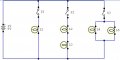
The idea is to design a basic lighting system with the following criteria:
-Main room has 3 lights in total- 1 light controlled by a switch & 2 lights wirted in parallel controlled by a second switch.
Bedroom 1- has 2 lights wired in series controlled by a third switch.
Bedroom 2- 1 light wired in parallel with 2 lights wired in series all controlled by a fourth switch
Bathroom has 1 light controlled by a fifth switch.
Here is the problem
only 1 9volt battery may be used to power all,
only 1 wire to each terminal on the battery (no junction boxes permitted, negates the idea of the project lol)
All 5 sets of lights must be wired in parallel with one another using a minimum of wire.
There is my dilema, any help or guidance is greatly appreciated....thank you in advance form the electrical nooblet lol..
Cheers!!!!
My daughter has turned to me for help with her homework project for Science class and alas I'm at a total loss.
The idea is to design a basic lighting system with the following criteria:
-Main room has 3 lights in total- 1 light controlled by a switch & 2 lights wirted in parallel controlled by a second switch.
Bedroom 1- has 2 lights wired in series controlled by a third switch.
Bedroom 2- 1 light wired in parallel with 2 lights wired in series all controlled by a fourth switch
Bathroom has 1 light controlled by a fifth switch.
Here is the problem
only 1 9volt battery may be used to power all,
only 1 wire to each terminal on the battery (no junction boxes permitted, negates the idea of the project lol)
All 5 sets of lights must be wired in parallel with one another using a minimum of wire.
There is my dilema, any help or guidance is greatly appreciated....thank you in advance form the electrical nooblet lol..
Cheers!!!!