Simple DC Motor Controller Burnout

Thread Starter

BobbyTheD

Joined Mar 10, 2016
37
Hi -
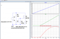
I recently built some very basic linear motor drivers, pretty much identical to the schematic below.
The only difference is that I built four of them and based them all on a single power supply - a USB-C Portable Rechargable Battery.
This had been working fine with very small toy DC motors. Recently, I plugged in a larger motor - still rated for 12v and all of the Mosfets burned out, except for the one powering the large motor.
I'm hoping someone can explain why this happened and if there's a way to prevent it from happening in the future, if I rebuild the circuit.
Thanks!


motor-speed-controller-compressed.jpg
 

Irving

Joined Jan 30, 2016
3,845
That's a very unusual arrangement; do you understand how that circuit is supposed to work?

When you say the MOSFETs burned out, how did they fail?
 

Thread Starter

BobbyTheD

Joined Mar 10, 2016
37
Attached a slightly cleaner version of the schematic - I thought it was actually a pretty standard driver, so I'd be very curious to know what other people use.

Essentially, 3/4 MOSFETs smoked up and suddenly, there was no speed control on the motors - they were just fully "ON", regardless of the potentiometer position.
 

Attachments

LesJones

Joined Jan 8, 2017
4,174
Can I confirm that my understanding of your problem is correct. You have a number of these circuits driving small motors and up this point they all worked. You then added another one of these circuits but with a larger motor. When you added this circuit all the ones with small motors failed but the one with the large motor worked. On the face of it it does not make sense. I assume that all the circuit must be connected together in some way. If not how could the circuit with the large motor have any effect on the existing circuits with small motors. Can you tell us how much current the small motors and the large motor draw ? Also do you have heat sinks on the mosfets. As the mosfets are just behaving as variable resistors they will generate heat due to the power that they have to dissipate. It would be better to use pulse width modulation to reduce the amount of power that has to be turned into heat.

Les.
 

Thread Starter

BobbyTheD

Joined Mar 10, 2016
37
Hi there -
Let me see if I can answer all of this..
I have four of these circuits built on the same board, powered by the same supply. The motors I am using have generally been pretty weak toy motors, but I recently tried plugging in a Johnson HC970, which is rated for about 2w. This was working fine on its own, but upon plugging in other motors, the board smoked up and the other controls ceased working.
I do not have heatsinks. I am also not using any sort of Schottky Diode currently, which I suspect is at least one big part of the problem. I'm hesitant to build out the whole circuit again (and burn through a bunch of MOSFETs), though, until I feel very confident that I've anticipated as many problems as possible.
I cannot use PWM for this project because high-frequency oscillation is a problem.
 

LesJones

Joined Jan 8, 2017
4,174
Your circuit in post #1 will never be able to apply the full supply voltage to to the motor as the gate has to be a few volts positive of the source. (An IRF540 has a threshold voltage of between 2 and 4 volts so it need to be greater than that for it to conduct well.) The second circuit with the motor in the drain part of the circuit in post #3 is better as you can switch the mosfet fully on.
Did you re connect the small motors with power on to the circuit ? Even if a voltage transient occured when connecting the small motors and that caused the mosfets to fail source to drain short circuit it should not have caused the mosfets to get so hot that they smoked as the motors should have limited the current. I suspect you may have had a short somewhere on the board directly to the + 12 volt rail. One other remote possibility is if it was the second circuit AND the potentiometer was at the +12 volt end of the track and the mosfets had failed with a gate to source short that could have caused large current to flow through the mosfet.

Les.
 

Thread Starter

BobbyTheD

Joined Mar 10, 2016
37
I put in new MOSFETs and some 4001s. I resoldered anything that looked loose. Things seem to be working ok - except it's producing a tremendous amount of heat. I was anticipating some - but I suspect this is too much.
Is it possible to do what I'm trying to do with the power supply that I'm using? Would a heat-sink suffice?
 

Irving

Joined Jan 30, 2016
3,845
I'm confused - the circuit in post #1 and that in #3 are completely different and work in completely different ways...
but both have the limitation that they are running the MOSFET in its ohmic region which most switching MOSFETs are not intended to do. Losses in the MOSFET generate heat and most TO220 cased devices will die above 2W without heat-sinking.

This is the wrong way to control motor speed... its hugely inefficient.

PWM is the correct way to do this...
 

Irving

Joined Jan 30, 2016
3,845
Is it possible to do what I'm trying to do with the power supply that I'm using? Would a heat-sink suffice?
PSU is fine, its the approach that's wrong. A bigger heat-sink would reduce the MOSFET death rate but won't reduce the heat generated. Using a MOSFET as a big variable resistor is hugely inefficient on anything bigger than an LED, and even then we don't dim LEDs this way.

There are specialist 'linear' MOSFETs for things like electronic loads but these are generally expensive. Most normal MOSFETs want to be either fully ON or fully OFF, not in between...

Controlling a motor this way has another problem... you get no torque at low speeds because you are limiting the current the motor can draw - I'm guessing your motors were off load. Put a load on them and you'll find they wont start at low settings.

Any motor controller you buy will be PWM-based...
 

MaxHeadRoom

Joined Jul 18, 2013
28,619
The circuit in #7 only costs about $3 to $5 and if you already have parts on hand, you are ahead of the game, the 555 only cost just over a $1 in many places.
 

Thread Starter

BobbyTheD

Joined Mar 10, 2016
37
So there is absolutely no other way to variably control these motors than with PWM?

I feel like I am beating my head against a wall with this problem: PWM generates a high-frequency whine through the motors that become a big issue when being used for the purpose that I am using them for. I have tried changing the frequency into various ultrasonic regions, but the problem remains that they are just too noisy.
 

MaxHeadRoom

Joined Jul 18, 2013
28,619
What switching frequency are you using?
I run 2.5HP T.M. motors with PWM and they are silent, maybe you are going too high, what is the lowest you have tried?
Picmicro suggest starting at around 6Khz. !
 

Irving

Joined Jan 30, 2016
3,845
Hmmm, its true PWM can generate a whine if the switching frequency is too low, but above about 10kHz you rarely get that unless there is a strange resonance in the motor windings (normally only on cheap motors). Pulse shaping can also help, but you won't get that with a simple controller.
 

Thread Starter

BobbyTheD

Joined Mar 10, 2016
37
I am using these motors with electromagnetic transducers, so they are very sensitive to stray signals - and there tends to be a lot of different heterodyning effects, even with ultrasonic frequencies.
I have built a basic 555-driven PWM motor controller and tried switching through a dozen capacitors without much luck.
I'd be willing to try and build a different "make" - or if you could suggest a commercial product that would handle this effectively, I'd be very interested.
As for the types of motors, generally-speaking they are on the cheaper side, but this is the one that started to introduce the trouble:
https://vikiwat.com/en/dc-motor-jonson-hc970-12vdc-l-75mm-50mm.html
 
Last edited:

MaxHeadRoom

Joined Jul 18, 2013
28,619
That is one of the better know, or at least popular Chinese DC motors, the same manuf as the 2.5 HP T.M. motors.
I have never experienced any audible effects from the ones I used, but my ears are getting up there in age, so maybe are alot less sensitive:(!
 

LowQCab

Joined Nov 6, 2012
4,029
The first "A-Number-One" issue You need to deal with is to
NEVER operate a Transistor without a Heat-Sink.
And especially when using them as a "Resistor".

The Second issue is You are using a "Brushed" Motor.
Brushed-Motors can generate RFI-Spikes way up into the Mhz range,
at up to ~4X the Supply-Voltage that is feeding the Motor.

Your ~50-Volt 4001's are probably already smoked,
use a C3D02060F-ND 600V Zero-Recovery-SiC-Diode,
they're only ~$1.60, and would be bullet-proof in your application,
and might even provide You with a slight Power-Boost.

You also need to put various sizes of Ceramic-Capacitors across the Motor-Leads,
10uf, + 100nf, 10nf, 1nf,
to suppress the generated RFI / Spikes.
If You go with PWM, don't use the 10uf or the 100nf,
instead use a couple of Ferrite-Beads on the Motor-Wires,
they can be used with PWM or Resistive Control.
The 10uf Cap will create a noticeable increase in Motor-Power.

If You do these 2 things, You probably won't smoke any more FETs.

PWM is a far superior speed control method, and will create much less HEAT.
.
.
.PWM Comparitor .PNG
 

Thread Starter

BobbyTheD

Joined Mar 10, 2016
37
OK - so, if I use the recommended diode, heat sinks, and some capacitors, I should be OK?

I'm using these with a RAVPower USB-C Power Pack, rated at 27000mAH - I just want to make sure I'm not running into my problem because I'm trying to draw too much power out of it with all these motors.

I will experiment with the dual-Op Amp PWM - maybe it's quieter than the 555 - but are there any other options that would be worth investigating?
 
Top