Signal Generator Distortion (square wave distorting at high freq) - HP/Agilent 33120A

Thread Starter

donatosd

Joined Mar 31, 2009
13
Hi everyone,

I am new in this forum and would like to start of by making a thread of a matter in which I need assistance.

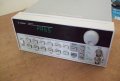
I am in search of a used Agilent/HP 33120A arbitrary signal generator.
I have found quite a few for sale on the internet, but I need help on deciding which ones are in good working condition and are safe to buy.

When the signal generator powers up, it performs a "limited" self-test. There is also a more complete self test that can be done, by holding down the "SHIFT" button and then pressing the power on button.

But I believe this is not enough.

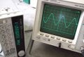
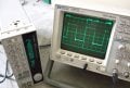
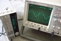
I have asked the sellers to also take some readings of the signal generators's output with an oscilloscope on the maximum available frequencies for each waveform type.
ie. sine wave at 15Mhz
square wave at 15 Mhz
Triangle wave at 100KHz (that is it's max freq.)

Have I done correctly??
Should I have some other test done?
It is not a cheap unit, so I want to make sure to get a good working unit and not a malfunctioning machine!!!!!
Someone please help me out here!!!!

PS. I have not specified at which voltages for which to test at.
Also I have not asked for testing of the waveforms at lower frequencies.
 

Thread Starter

donatosd

Joined Mar 31, 2009
13
He has sent me some pictures which I have attached in this post.
All looks well, except for the square wave, it looks fine at 500KHz but at 15MHz it becomes wildly distorted. Sine looks good at 15MHz.

Does anyone know what is causing this distortion on the square wave?

It looks like he is using a bnc-to-bnc cable for connecting the scope to the generator.

1)Could the cable be the problem?
(not designed for high frequencies? but sine wave is good at that freuqency!)

2)Or is it a fault in the signal generator? (could it be fixable?)

3) maybe it justs needs calibration?

can anyone help out here?!!!!

any help would be greatly appreciated!!!!

thanks!
 

Attachments

Looks like an impedance mismatch - the output of the gen should be 50 Ω series terminated, the cable should have a characteristic impedance of 50 Ω, and the 'scope should be 50 Ω parallel terminated. This will of course halve the voltage at the output, but the reflections should be minimal.

I can't tell the o/p impedance of the gen. The cable is probably 50 Ω (might be 75 Ω, but it's unlikely). The 'scope looks like it's set to a standard 1 MΩ input.

You can see some ringing on the edges of the lower frequency square wave - increase the frequency to 15 MHz and the effects of this ringing will become more apparent.

Sine waves invariably look nice - they're not a good test of signal integrity.
 

Thread Starter

donatosd

Joined Mar 31, 2009
13
Thanks Darren for the quick response!

Yes I saw the ringing on the square wave...
but, the distorted square waveform that I was talking about was in the 4th picture...the heavily distorted one (the one taht looks like a distorted sine wave!)!!! That is actually a square wave at 15MHz.!!


what is causing the problem? impedance mismatch? or does it need repair or calibration?
 
donatosd, we're both talking about the same 15 MHz square wave pic, we're just looking at it a bit differently. If 15 MHz is near the top end of the freq spec then I's expect slew-rate limiting on the edges; add to that some ringing of the same ballpark frequency and you have what looks like a distorted sinewave. Or a slew-limited square wave with non-harmonic frequency components.

The only real way to make sure is to see the response with proper signal terminations. That said, by inference it looks OK to me. But then it's not my money...
 

Thread Starter

donatosd

Joined Mar 31, 2009
13
15MHz is the Signal generators max frequency for square and sine wave forms.

but the sine wave looks ok at the same frequency....
 
It's the ∂V/∂t that stimulates the ringing in an impedance-mismatched transmission line, and there's not enough of that in a 15 MHz sine wave to show up here. But the square wave has faster edges than a sine wave of the same frequency.

Sine waves aren't good test signals for signal integrity issues, as the fastest rates of change are at the zero crossing points, and those are slow compared to any respectable square wave of the same frequency. And once you go into the multi-MHz range, square waves are never quite square either, there are too many non-idealities.
 

Thread Starter

donatosd

Joined Mar 31, 2009
13
well I greatly appreciate your help Darren!

So I guess it pretty safe to say it is a impedance mismatching problem, or maybe just a simple calibration needed to get it working properly.

I will probably end up buying from him, since he is the only seller to actually send any pictures at all! and since it has a pretty decent square wave response up to 500KHz (and prob a little more) and a good price!

thanks again, and have a good day!!!
 
Top