Signal detector

Thread Starter

Fedka

Joined Jan 5, 2021
7
Hi, everybody.
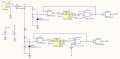
I'm trying to make a detector, that gets two-part signal and it drives two output signals (LEDs) that visually indicate that both parts of input are exist. When some part is absent, the appropriate LED is off.
1-part is sinusoid Vptp=60V, f=1Mhz. Full length of this part is not important.
2-part is 3÷5 pulses Vmax=+1260V÷2310V, Vmin=-600V, Pulse_width=200ns÷500ns.
I tried to rectify and reduce input and count some pulses from the first part (I suppose that if there are dozen pulses, that it's OK) and at least three pulses from the second part.
Guess what? It does not work. The first part is detected somehow, but it clears at the end, because the second part produce an enormous noise in all the circuit and on the CLEAR line too. I checked this with signal with no second part - the first LED remains ON. The second part is not detected at all, because when reduces at the point "Z2" it became a simple noise.
Pls, advise what can be done. May be this way is totally wrong and should be done in other way.
Thank you.
 

Attachments

KeithWalker

Joined Jul 10, 2017
3,091
I don't understand the nature of your input signals from your description:
"2-part is 3÷5 pulses Vmax=+1260V÷2310V, Vmin=-600V, Pulse_width=200ns÷500ns."
Is that +1260/2310?
Is waveform 1 modulated by waveform 2 when they are both present?
Can you sketch a waveform diagram of each possible input combination, with scaled axes to clarify this?
 

michael8

Joined Jan 11, 2015
414
I'm assuming since you provided a scope picture that this is a real circuit, not (just) a simulation.

Your inputs span a 2100 volt range (+1500 to -600 volts). This is not the normal range for "normal" components, nor
"normal" layout. A picture of your circuit as built would help. Include the input wires for some distance too,
as those pulses will couple to anything near them (like the +5 power). The shared ground line also implies
more coupling...

Components have limits. Your D1 is only a 600 volt diode. Normal resistors (smd? through hole? type?) can only
handle at most a few hundred volts. So your input(s) to your logic chips are undefined/unknown.

The counter "clear" is floating (not high or low)? I just see it connected to a capacitor to ground.
 

Thread Starter

Fedka

Joined Jan 5, 2021
7
I don't understand the nature of your input signals from your description:
"2-part is 3÷5 pulses Vmax=+1260V÷2310V, Vmin=-600V, Pulse_width=200ns÷500ns."
Is that +1260/2310?
Is waveform 1 modulated by waveform 2 when they are both present?
Can you sketch a waveform diagram of each possible input combination, with scaled axes to clarify this?
The meaning of "Vmax=+1260V÷2310V" that it could be any value from 1260V to 2310V.
The picture of waveform is attached on the top.
 

Thread Starter

Fedka

Joined Jan 5, 2021
7
I'm assuming since you provided a scope picture that this is a real circuit, not (just) a simulation.

Your inputs span a 2100 volt range (+1500 to -600 volts). This is not the normal range for "normal" components, nor
"normal" layout. A picture of your circuit as built would help. Include the input wires for some distance too,
as those pulses will couple to anything near them (like the +5 power). The shared ground line also implies
more coupling...

Components have limits. Your D1 is only a 600 volt diode. Normal resistors (smd? through hole? type?) can only
handle at most a few hundred volts. So your input(s) to your logic chips are undefined/unknown.

The counter "clear" is floating (not high or low)? I just see it connected to a capacitor to ground.
Yes, it's real circuit. Please, see picture of the board in attachment.
I'm not limited to any type of the components. It could be surface mount or trough hole. The size of the board also can be bigger twice or even triple.
"CLEAR" is pulldowned.
I've attached the full circuit.
 

Attachments

michael8

Joined Jan 11, 2015
414
I've thought about this some more, and while I haven't built anything
near this, I've read a lot. I have more questions and some thoughts:

What hardware and how was it connect to get that scope picture without
damaging the scope?

What is the cable from the source to your circuit? Is it a separate coax?

The input is:

1. 60 volt 1 MHz sine wave burst

2. +2310 to -600 volt 200 nS pulses

2310 volt pulses will fry just about any semiconductor as well as just
make them misbehave.

You don't want your circuit to be damaged or not work due to these (or
similar) inputs, and you're just trying to detect these, not measure them
so absolute accuracy isn't important.

I'd try to minimize the amount of circuitry which needs to deal with
the high voltage. So the first thing is I'd attenuate it down to some
reasnable level. Considering your 5 volt power I'd suggest something
less than 5 volt. So perhaps a factor of 500.

This takes the 2310 volts down to 4.6 volts, and the -600 volts to
-1.2 volts. The 60 volt signal results in 120 mV which is still a
reasonable signal level.

Your signals are all AC so this attenuator could be a capacitive divider,
say 1 pF in series with 500 pF to ground. The 1 pF could be a "gimic"
capacitor constructed with HV wire.

https://en.wikipedia.org/wiki/Gimmick_capacitor

I'd use a normal (few hundred volt) capacitor for the 500 pF capacitor
to ground (part of this capacitance could be the capacitance of the next
input stage). Perhaps a 1 meg ohm resistor from the midpoint to ground
to provide a DC level for the following comparator.

That's as far as I've gotten so far, it's still an AC signal with positive
and negative values possible and needs to be converted to digital signal
and then be processed by some digital logic...
 

Thread Starter

Fedka

Joined Jan 5, 2021
7
I've thought about this some more, and while I haven't built anything
near this, I've read a lot. I have more questions and some thoughts:

What hardware and how was it connect to get that scope picture without
damaging the scope?

What is the cable from the source to your circuit? Is it a separate coax?

The input is:

1. 60 volt 1 MHz sine wave burst

2. +2310 to -600 volt 200 nS pulses

2310 volt pulses will fry just about any semiconductor as well as just
make them misbehave.

You don't want your circuit to be damaged or not work due to these (or
similar) inputs, and you're just trying to detect these, not measure them
so absolute accuracy isn't important.

I'd try to minimize the amount of circuitry which needs to deal with
the high voltage. So the first thing is I'd attenuate it down to some
reasnable level. Considering your 5 volt power I'd suggest something
less than 5 volt. So perhaps a factor of 500.

This takes the 2310 volts down to 4.6 volts, and the -600 volts to
-1.2 volts. The 60 volt signal results in 120 mV which is still a
reasonable signal level.

Your signals are all AC so this attenuator could be a capacitive divider,
say 1 pF in series with 500 pF to ground. The 1 pF could be a "gimic"
capacitor constructed with HV wire.

https://en.wikipedia.org/wiki/Gimmick_capacitor

I'd use a normal (few hundred volt) capacitor for the 500 pF capacitor
to ground (part of this capacitance could be the capacitance of the next
input stage). Perhaps a 1 meg ohm resistor from the midpoint to ground
to provide a DC level for the following comparator.

That's as far as I've gotten so far, it's still an AC signal with positive
and negative values possible and needs to be converted to digital signal
and then be processed by some digital logic...

1. The source is always connected to the 200Ω load. I.e. input of my circuit is always in parallel to the 200Ω.
2. The pulse is short, therefore it doesn't have much energy. The signal is generated by medical device and applied on the human body. The energy for this pulse is accumulated by buck-booster. It has a fat burning effect and for the last 7y still nobody was killed :)
So while measured it's connected to the scope by the regular probe. And to the 200Ω in the tester by 22 AWG wire.

Why capacitor divider is better for our purposes, than resistor one?
 

michael8

Joined Jan 11, 2015
414
Why capacitor divider is better for our purposes, than resistor one?

Several reasons. You can't get a resistor which doesn't have capacitance in parallel with it. At the resistance values
you would need for your input divider more current would travel via the capacitance around the resistor
than through it since your signals are high frequency AC. You would need to add capacitors across the resistors to
make the resistive divider work for AC. Take a look at how x10 scope probes work.

Also normal resistors have a voltage limit of something in the 100 to 350 volt range. So you would need a series
string to be able to handle your 2300 volts.

The HV wire "capacitor" gimic avoids special HV parts other than the HV wire. Oh, an alternative capacitor would
be a cm or so of coax, using the capacitance between the center and shield as the HV capacitor. You'd need coax
which could handle the voltage. Here's a link to a spec for RG8 which says it can take 4KV and has 29.6pF/foot.

https://www.awcwire.com/rg-catalog/rg8-coax-cable

It's 2am here, goodnight..
 

michael8

Joined Jan 11, 2015
414
Vishay has some series of high voltage resistors. See the attached datasheet for more info.

Are they inductive? I don't see any capacitance specification. Here's a simulation of a 1/500 voltage divider
made with resistors (assumed to be non-inductive) but with 1pF of parallel capacitance across each resistor.

res-div1.png
 

Attachments

michael8

Joined Jan 11, 2015
414
So while measured it's connected to the scope by the regular probe. And to the 200 ohm in the tester by 22 AWG wire.

I'm trying to understand the signal. If this was a "normal" x10 probe then the 1500 volts would be only 150 at input to the scope (assumes that the probe's x10 really works for 1500 volt inputs). Is that how the scope photo was taken?

With a 200 ohm load, the currents are:

60 volts @ 1 MHz -> 300 mA
1500 volts for 200 to 500 nS -> 7.5 A

I have questions about the source interactions/connections with the detect circuit ground. Do they use the same
ground? The same +5 volt power?

Here's a possible simulation of the source & an input approach. The xsig is inside the +5 volt detect range.

Note that there is mA of current through the 0.8pF capacitor...

source2.png


(This is using LTspice, a free circuit simulation program)
 

Attachments

Thread Starter

Fedka

Joined Jan 5, 2021
7
So while measured it's connected to the scope by the regular probe. And to the 200 ohm in the tester by 22 AWG wire.

I'm trying to understand the signal. If this was a "normal" x10 probe then the 1500 volts would be only 150 at input to the scope (assumes that the probe's x10 really works for 1500 volt inputs). Is that how the scope photo was taken?

With a 200 ohm load, the currents are:

60 volts @ 1 MHz -> 300 mA
1500 volts for 200 to 500 nS -> 7.5 A

I have questions about the source interactions/connections with the detect circuit ground. Do they use the same
ground? The same +5 volt power?

Here's a possible simulation of the source & an input approach. The xsig is inside the +5 volt detect range.

Note that there is mA of current through the 0.8pF capacitor...

View attachment 249660


(This is using LTspice, a free circuit simulation program)
Yes, it's x10 probe.
I think I know what is the issue.
In our board signal and power supply have the same GND. And, I suppose, this is the source of the problem. Because the source for signal is floating.
I will place high frequency transformer to isolate signal from board.
 

Thread Starter

Fedka

Joined Jan 5, 2021
7
Yes, it's x10 probe.
I think I know what is the issue.
In our board signal and power supply have the same GND. And, I suppose, this is the source of the problem. Because the source for signal is floating.
I will place high frequency transformer to isolate signal from board.

As it turned out, finding a 5Mhz transformer is problematic....
 
Top