 Facebook
 Google
 GitHub
 Linkedin
Is ground physically 0V or just a reference (like maybe 2.5V) that we use to measure voltages from?
Should i be grounding the VSINE or just take the voltage across it without the reference. Basically i have understood the connected ground is not actually 0V, but only a reference point, because only that would explain the voltage being same in both the circuits across the VSINE component.
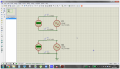
Without the ground on the VSINE, i can see that the voltage shown by the probes is same in magnitude but opposite in polarity, for example in the screenshot, -2.8V and +2.8V, which would give a Voltage difference of -5.6V, basically a point on the negative half cycle.
The same can be said of the circuit with the ground, now that i have made one terminal the ground (reference?).
What reference voltage is the probe taking in both the circuits?
Is all this thinking in the right direction?
Should i be grounding the VSINE or just take the voltage across it without the reference. Basically i have understood the connected ground is not actually 0V, but only a reference point, because only that would explain the voltage being same in both the circuits across the VSINE component.
Without the ground on the VSINE, i can see that the voltage shown by the probes is same in magnitude but opposite in polarity, for example in the screenshot, -2.8V and +2.8V, which would give a Voltage difference of -5.6V, basically a point on the negative half cycle.
The same can be said of the circuit with the ground, now that i have made one terminal the ground (reference?).
What reference voltage is the probe taking in both the circuits?
Is all this thinking in the right direction?
Attachments
-
 484.9 KB Views: 26


