 Facebook
 Google
 GitHub
 Linkedin
Hi,
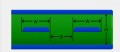
I am designing a PCB of project that involves USB 2.0 differential pair trace. It is a 4-layer board with the following configuration:
Top layer: Analog and low-speed digital signal
Layer 2: 3.0V Power plane
Layer 1: USB2.0 Differential pair trace
Bottom layer: Ground plane
Also shown in the following figure.

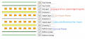
I am planning to use Saturn PCB to calculate the impedance of the USB 2.0 differential pair, as shown below.

However, I am not sure whether should I use symmetric stripline impedance for the impedance calculation, because according to this:

http://www.bitweenie.com/listings/microstrip-vs-stripline/
for a stripline, the transmission line is in between of 2 ground planes, however in my design, the transmission line is in between of a power plane and a ground plane.
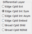
There are a few more choices for the calculation provided by Saturn PCB Toolkit as shown below.

I would like to know which one should I select for the USB 2.0 differential pair impedance calculation.
Thank you.
I am designing a PCB of project that involves USB 2.0 differential pair trace. It is a 4-layer board with the following configuration:
Top layer: Analog and low-speed digital signal
Layer 2: 3.0V Power plane
Layer 1: USB2.0 Differential pair trace
Bottom layer: Ground plane
Also shown in the following figure.
I am planning to use Saturn PCB to calculate the impedance of the USB 2.0 differential pair, as shown below.
However, I am not sure whether should I use symmetric stripline impedance for the impedance calculation, because according to this:
http://www.bitweenie.com/listings/microstrip-vs-stripline/
for a stripline, the transmission line is in between of 2 ground planes, however in my design, the transmission line is in between of a power plane and a ground plane.
There are a few more choices for the calculation provided by Saturn PCB Toolkit as shown below.
I would like to know which one should I select for the USB 2.0 differential pair impedance calculation.
Thank you.
Attachments
-
 18.6 KB Views: 1
 -
 25.9 KB Views: 1
 -
 6 KB Views: 1


