Series-Shunt Feedback Amplifier

Thread Starter

jegues

Joined Sep 13, 2010
733
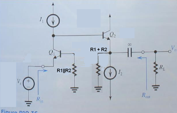
I think I managed to get part a), but I'm stuck on part b).

I wrote all the equations I could think of in the circuit but I'm still a little stuck as to actually solving the DC emitter currents. Is there an assumption I can make about any of the other currents?

For example,

Can I assume,

\(I_{c1} \approx I_{1}\)

Is this acceptable? Or should I be able to solve for everything?

I feel like I need to solve 1 value or make an assumption in order to get things rolling.

Thanks again!
 

Attachments

t_n_k

Joined Mar 6, 2009
5,455
For the currents you can do an incremental approach.

First assume IB1≈0.

Then calculate the current in R1=0.7/1k=0.7mA. Hence current in R2=0.7mA and hence it follows that IE2=1.7mA.

Thus IB2=1.7mA/101=16.8uA.

This makes IC1=100uA-16.8uA=83.2uA. Thus IB1 would be better approximated as 832nA.

You could redo the process now using IB1=832nA rather than IB1=0A. But I doubt things would change that much.
 

Thread Starter

jegues

Joined Sep 13, 2010
733
The closed loop gain should be ~100.
How did you draw this conclusion?

I've been reading in the book how to estimate the closed loop gain when we have a large loop gain but obviously I found the wrong relationship.

My reasoning was as follows,

\(A\beta \rightarrow \infty\)

\(A_{f} = \frac{V_{o}}{V_{s}}= \frac{A}{1+A\beta} \Rightarrow \frac{A}{A\beta} = \frac{1}{\beta}\)
 

t_n_k

Joined Mar 6, 2009
5,455
Begging your pardon - it should be ~10 rather than ~100. I slipped an order of magnitude in my original "back of the envelope" estimate.

Basically, I'm looking at what happens at the output emitter (E2) as the input varies.

With the input 0V then VB1≈0.7V and hence VE2≈7.7V.

If the input increases from 0V to +10mV then VB1=0.71 V and hence

VE2=7.1+0.71=7.81V.

So the VE2 has changed by (7.81-7.7) 0.11V for a 10mV input change, which equates to a gain of Av=0.11/0.01=11.

If the input is -10mV then VB1=0.69V and VE2=6.9+0.69=7.59V

So for a change from 0V to -10mV the E2 voltage changes by 7.7-7.59=0.11V - again indicating a small signal gain of ~11.
 

t_n_k

Joined Mar 6, 2009
5,455
Using the idea of feedback you can come up with the gain as follows.

If the open loop gain is Avo then

\(V_o=A_{vo}\[V_s-\frac{R_1}{(R_1+R_2)}V_o\]\)

Re-arranging this gives

\(V_o\[1+A_{vo}\frac{R_1}{(R_1+R_2)}\]=A_{vo}V_s\)

or

\(V_o\[\frac{1}{A_{vo}}+\frac{R_1}{(R_1+R_2)}\]=V_s\)

And if Avo is very large then

\(V_o\[\frac{R_1}{(R_1+R_2)}\]=V_s\)

and finally

\(A_f=\frac{V_o}{V_s}=\frac{(R_1+R_2)}{R_1}\)

So Af=11 with the given values looks consistent.

Perhaps you have confused the transistor current gain beta values with the feedback beta factor.

i.e.

\(\beta=\frac{R_1}{(R_1+R_2)}\)
 
Last edited:

Jony130

Joined Feb 17, 2009
5,488
I was bored today so I decided to find open loop voltage gain.

I use this diagram


And I assume Ic1 = 100uA; Ic2 = 1.6mA

re1 = 26mV/100uA = 260Ω

re2 = 26mV/1.6mA = 16.25Ω

So the voltage gain of the first BJT is equal

\( A1 = \frac{Rc}{re} = \frac{( hfe+1)*(re2 + R1+R2)}{re1 + \frac{R1||R2}{Hfe+1} } = 4.13K \)

And I'm not sure whether this (R1||R2)/(Hfe +1) should be take into account.

Voltage gain for Q2 is equal


\( A2 =\frac{Re}{re+Re} = \frac{R1+R2}{re + R1+R2} = 0.998 \)

So open loop gain

Ao = A1 * A2 = 4.12KV/V

The input resistance

\( Rin = {re1 + \frac{R1||R2}{Hfe+1} } = 269\Omega \)

So after we close the feedback loop the voltage gain will drop to:

Af = Ao/ ( 1 + Ao*β ) = 10.97 V/V

and

Rin_f = Rin* = 101KΩ

Rout_f = (R1+R2) /
(1+ Ao*β) = 29.3Ω But I also not sure about that.

So what do you think about my simplified analysis?
 

t_n_k

Joined Mar 6, 2009
5,455
Thanks for your useful analysis Jony130.

On the matter of which components to include in the open loop AC gain analysis one could perhaps assume that the feedback is 'killed' by shunting Q1 base to ground with a large capacitance. So the DC conditions would be 'preserved' but the AC gain would presumably more closely approach the open loop case.

Would that mean you then dispense with the (R1||R2)/(Hfe +1) term and replace the R1+R2 combination at Q2 emitter with just R2? Presumably yes.

In any event the open loop gain is highly dependent on the Q2 hfe value.

The addition of the load resistance RL to the circuit will also have an effect.
 

Thread Starter

jegues

Joined Sep 13, 2010
733
Perhaps you have confused the transistor current gain beta values with the feedback beta factor.

\(\beta=\frac{R_1}{(R_1+R_2)}\)
I think this the source of my confusion.

So the \(\beta_{1}, \beta_{2}\) are the transistor current gain beta values NOT the feedback beta factor.

Thanks again!
 
Last edited:

Thread Starter

jegues

Joined Sep 13, 2010
733
I've started working on part c),

\(R_{i} = R_{s} + r_{e1} + \frac{R_{11}}{\beta + 1} \quad ; \text{where} \quad R_{11} = R_{1}//R_{2}\)

\(R_{o} = R_{22}//R_{L} \quad ; \text{where} \quad R_{22} = R_{1}+R_{2}\)

Are these expressions correct?

How does one go about solving for A?

Thanks again!
 

Jony130

Joined Feb 17, 2009
5,488
\(R_{i} = R_{s} + r_{e1} + \frac{R_{11}}{\beta + 1} \quad ; \text{where} \quad R_{11} = R_{1}//R_{2}\)

\(R_{o} = R_{22}//R_{L} \quad ; \text{where} \quad R_{22} = R_{1}+R_{2}\)

Are these expressions correct?
It looks ok to me.


How does one go about solving for A?
Simply use classic method.
Replace BJT with his Hybrid-pi model and find the open loop gain.


And we can use "brutal force" nodal analysis to find the voltage gain.
I can write equation for Va node.

\(\frac{Vout - Va}{r_{\pi 2}} = \frac{ Va - Vin}{ro1} + gm1*(r_{\pi 1} *\frac{0-Vin}{R1||R2+r_{\pi 2}})\)

And for Vout node

\(\frac{Vout}{R1+R2} +\frac{ Vout}{ro2} +\frac{Vout-Va}{r_{\pi 2}} = gm2*(r_{\pi 2} * - \frac{Vout - Va}{r_{\pi 2}})\)

And when I solve this for Vout/Vin this is what I get
Additional I assume that ro1 = ro2 = ∞

\(\frac{Vout}{Vin}=\frac{gm1*(R1+R2)*r_{\pi 1}*(1 + gm2*r_{\pi 2})}{R1||R2 + r_{\pi 1}}\)

I also use another method. And I get similar solution.
The method I use is described here
http://forum.allaboutcircuits.com/showthread.php?p=165051#post165051 (43)
http://forum.allaboutcircuits.com/showthread.php?p=289293#post289293

From all this "methods" my "simplified method" (show in post 9 in thread) is the fastest one.
 

Attachments

Last edited:
I've started working on part c),

\(R_{i} = R_{s} + r_{e1} + \frac{R_{11}}{\beta + 1} \quad ; \text{where} \quad R_{11} = R_{1}//R_{2}\)

\(R_{o} = R_{22}//R_{L} \quad ; \text{where} \quad R_{22} = R_{1}+R_{2}\)

Are these expressions correct?

How does one go about solving for A?

Thanks again!
Be aware that the output impedance you have given is for the case where the source Vs is not connected to Rs; that is, with the left end of Rs not connected to anything. Assuming Vs is an ideal voltage source with zero output impedance, if Vs is connected to Rs, then Ro will be different. Which do you suppose the problem is asking for?

Also, if RL is connected, then the expression for Ri will include RL.
 

Thread Starter

jegues

Joined Sep 13, 2010
733
Be aware that the output impedance you have given is for the case where the source Vs is not connected to Rs; that is, with the left end of Rs not connected to anything. Assuming Vs is an ideal voltage source with zero output impedance, if Vs is connected to Rs, then Ro will be different. Which do you suppose the problem is asking for?

Also, if RL is connected, then the expression for Ri will include RL.
How am I supposed to decipher which the problem is asking for?

Based on the examples in the text, Vs nor Rs are considered when calculating \(R_{o}\).
 
Last edited:
How am I supposed to decipher which the problem is asking for?
Since you are the student, ultimately it will be up to you to determine. You could ask your instructor. I was asking if you had any way to know.

Based on the examples in the text, Vs nor Rs are considered when calculating \(R_{o}\).
That may be sufficient. However, since Vs would be driving the circuit when the load is connected, the output impedance with a source connected would seem to be relevant.

Did the other examples in the text you're referring to lack feedback? Perhaps they had output impedances that didn't change when the source was connected.
 

Jony130

Joined Feb 17, 2009
5,488
We here in Polad use this definition for Rout
Rout = Vout_open / Iout_short when Vs and Rs is replaced by a short circuit.
 
Top