Sennheiser IEM (Portable UHF Reciever) - constant tone

Thread Starter

niddnet

Joined Jan 16, 2018
15
Hi All,

First post, so I'll be very grateful if anyone can help me out.

I've just received a Sennheiser EW300 IEM G2 system for my repair / use.

For those who don't know, IEM is 'in-ear monitoring' - it's essentially a wireless headphone setup, comprising of a transmitter unit, and a little belt-pack, into which you plug your headphones (like singers wear).

The issue is that instead of any audio (AF), all I get from the headphones is a loud beep tone. Approx 900Hz, with a brief 'ramp up' time of about 0.5s. The tone is constant, and does not change in response to volume control, or any other front panel adjustments. Whenever there is power, the tone is there.

Additionally, it appears the audio amp stage is not functioning, because when I send audio from the transmitter, this is not heard at all.

Further, the receiver belt-pack itself (which, for clarity contains NO speakers, buzzers, etc.) also makes the exact same noise.

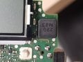
Usual tests and checks have shown nothing, other than it must be a fault on the power stage. The only reasonably large passive on the board is an inductor (labeled 220 M83) - presuming a 220uH - and guess what - THIS is where the noise emanates from.

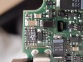
On the flip side of this inductor is a small IC (which I believe to be the DC-DC converter / VR) - (LTPG e3) 10 pin IC - so a Linear Tech.... something....

Whilst I'm adept at prodding things and gathering info, and reasonably good at theoretical diagnostic, I don't know where to go from here, so would welcome some input.

a) Is the inductor making noise because it is faulty, or because something else is faulty down the line?
b) How would I even measure to check an inductor is operating correctly? (I have meters, random spare passives, etc.)
c) I guess my next test will be checking the voltages on the test-points? (I also have the Service Manual)

If anyone can shed any more light, and can help me out - even at a chargeable rate, if the forum allows, I would really love to get this up and running. I am in the UK if that helps and will happily send data, schematics, and run whatever tests are required of me!

Thanks in advance,


Ross.
 

MrChips

Joined Oct 2, 2009
34,956
Presumably the headphones work when plugged into a different source.
It is unlikely that the inductor you mention is at fault. You have to look deeper into the workings as shown in the schematics.
 

AlbertHall

Joined Jun 4, 2014
12,636
Almost certainly the inductor is making a noise because of a fault elsewhere. Probably the first thing to check is the electrolytic capacitors around the inductor. Do you have a meter that can check capacitors?
 

Thread Starter

niddnet

Joined Jan 16, 2018
15
Hi MrChips

Indeed - the headphones are indeed fine. The fact that the unit itself is audibly making this noise with the headphones disconnected was what made me think it could be something internal, and with my (very limited) experience in such things, I've seen inductors on PSUs whining in the past (usually on LED drivers etc).

Hi Albert - thank you for your input. Yes, I have a reasonably good DMM and an equally good LACK of knowledge in using it efficiently. Am I right in saying that caps have to be measured out of circuit? These are all SMD.

I don't (yet) have a photo of the inductor side of the board, but I will attach a photo of what I believe to be the DC converter in my next post.

If you would like the Service Manual, please let me know; though I would prefer to send this privately, as I don't believe it's public domain.
 

Thread Starter

niddnet

Joined Jan 16, 2018
15
Nothing large about this unit sadly... the whole thing is approx 3" square.

I've just pulled it apart to get you some photos.

I hope these give you an idea, and you're able to point me in the right direction to begin to work this out!

Thanks again :)

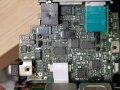
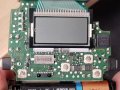
Rear of Board (inductor area).jpg Rear of Board.jpg Front Board (inductor).jpg Front Board.jpg
 

Thread Starter

niddnet

Joined Jan 16, 2018
15
Voltage checks as per service manual:

Digital side
+5.0vdc - ok
+3.3vdc - ok

RF side:
+2.9vdc - ok
+5.0vdc - ok
+5.5vdc - ok

Analog / AF side:
+2.8vdc - ok
+5.4vdc - 0.0vdc - 0.8v~ 950Hz. (that's the same tone I hear from the inductor, and out the headphone out.)

According to the SM, the 5.4vdc rail powers the audio amp side of things - so I know I'm on the right track.

The chip, it turns out, is an L3401 (http://cds.linear.com/docs/en/datasheet/3401fb.pdf) - output within spec of the SM.

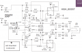
I have uploaded the schematic now - I'm not much good at reading anything this complicated.

My understanding is that I can't check caps out of service - and some of these caps and resistors are just too tiny for me to manage with.

I could just about have coped with replacing the L3401, but the rest - no chance.

Looking at the attachment, is there anything that has a higher likelihood of failure (or certainty??) that I can concentrate on?

Failing that, what about getting another supply from elsewhere on the board? either the 5v digital or 5.5v RF feed?

To be honest, I wouldn't be against grafting in a completely separate supply if it came to it.

So - in summary - all DC lines are good *except* 5.4vdc (measured at TP23) - which according to SM says is the power rail for the audio amp.

I'm slightly out of my depth, but also tantalisingly close to getting it to a result too I think!!
 

Attachments

AlbertHall

Joined Jun 4, 2014
12,636
Is the 5.4V also missing at TP21?
The difficulty here is that it may be the power supply which has the problem, or something may be drawing too much current and pulling the supply down and it is difficult to establish which is happening.
 

Thread Starter

niddnet

Joined Jan 16, 2018
15
Albert

TP21 seems to be directly out of the L3401 IC if I'm correct?

The service manual says TP21 should be between 5.2 and 5.6 and it is within these parameters. I've reassembled now, so as not to lose the tiny screws and buttons.

Is it that the vOut from the IC (TP21) is proportionate with the battery voltage to a degree, so they further regulated at TP23?

I don't know what the gubbins is between that vOut and TP23 and the 5.4v rail!

Many thanks for your continued help


Ross
 

Thread Starter

niddnet

Joined Jan 16, 2018
15
Just as a final thought before I sleep, is there any component I could remove / lift a leg to isolate power to that rail or the audio amp? Just so I could easily test the audio side?

(I was thinking I could use a bench supply, just heavily limit current just in case...)

Also, the inductor that seems to make the most noise is the one which is shown next to the IC on the schematic - I don't know if that's relevant or not, but wanted to add it for completeness.
 

AlbertHall

Joined Jun 4, 2014
12,636
The 'gubbins' is/are switches that enable power to the rest of the circuit.
Q4 switches the power to TP22 - check the voltage here.

Then the two Q5s and Q6 switch that power to TP23.
(There are two transistors identified as Q5!)
I think the leftmost Q5 connects the power through R108 and R109 to get limited power, then Q6 can switch on full power. I am not sure why they would have that two level switching at the moment though. Cross that bridge when we need to.
 

Thread Starter

niddnet

Joined Jan 16, 2018
15
I'll check TP22 as soon as I'm home.

I've also attached the schematic for the audio amp itself.

Seems the L&R audio signal are sent along the lines with TP184 and TP284 and the 5.4V rail (the dead one) then powers U21 (which is an IC - http://www.ti.com/lit/ds/symlink/lm4808.pdf ) audio amp, and if that's buggered, I'm going to be sad!)

Not expensive to replace, but beyond my skills I would think... I need to get some old boards and start practising with SMD and hot-air.

I don't know if the attached helps any further with the task in hand, but if not helping here, it may help others in future.

Thanks again!

Ross
 

Attachments

LesJones

Joined Jan 8, 2017
4,509
I have a suspicion that the overvoltage or overcurrent protection could be shutting the switch mode regulator down and then allowing it too try to restart ar the 900 hz frequency. (This is much lower than the switching regulator frequency which I think was a few Mhz from the LTC3401 data sheet.) Would it be possible to disconnect the 5.4 volt feed to the audio amps ? Another possibliity is that the batteries have become high internal resistance whick may cause the problem. Do you have an oscilloscope to see if the output of the LTC3401 is mdulated with the 900 hz ?

Les.
 

Thread Starter

niddnet

Joined Jan 16, 2018
15
Hi Les.

That's one of my questions too - Id like to know if there's a way to isolate the 5.4v rail so I can try and run the audio amp from the bench supply.

I don't have a scope but I can rig up a small audio probe that can handle the DC to hear if theres any AC or noise on the main output. My dmm shows 0vac at the output test point (TP21) with the DC reading within range.

I'm learning a lot here!
 

LesJones

Joined Jan 8, 2017
4,509
I was hoping that the audio amp was on a separate board so you could just disconnect a wire. If it is on the board in the pictures I think it will be difficult to isolate. Wile looking at the pictures of the board it looks like the batteries are AA cells so I don't think my high resistance battery theory is valid. (I was thinking it used a built in rechargable battery that was very old.) You seem to be doing all the right things. I also sometimes use the AC range on a meter to look for ripple on a DC rail.

Les.
 

Thread Starter

niddnet

Joined Jan 16, 2018
15
Referring back to Albert's post before and re-testing (see below):

TP21 - 5.430vdc. (from VR)
TP22 - 5.413vdc. (from Q4, fed by VR)
TP23 - 0.610vdc. (rail for audio amp)

Back-tracking to double-check now I've been able to find better points to test things (TPs rather than legs of SMD components) I checked the DC output directly at TP21, TP22, and TP23 and they are showing approx 130mV AC atop of the DC voltage above that is put out. Frequency of the AC - 950Hz, give or take. The same noise which is heard.

So it might be that which is preventing the power at TP23? Though even being noisy as hell, there is still a good DC voltage coming out of the DC-DC.

Is it likely that the L3401 is actually the suspect after all? And it could be the noise that's preventing the supply to the amp rail (TP23) after all?

Or I suppose equally likely that something bringing down the amp rail (TP23) could be causing the L3401 (and associated passives) to go into oscillation?

One thing I haven't checked, is the current draw from the actual batteries. If it's unusually high, that could indicate the latter I guess?

I'll come back to you with results.
 

Thread Starter

niddnet

Joined Jan 16, 2018
15
Results:

Holy current drain, Batman.

I thought I imagined the AA batteries having a slightly elevated temperature.

With a pair of brand new alkalines (1.605VDC each) the current draw is 459mA.

Service manual states "129mA at nominal voltage without modulation." Nominal is 2.4VDC - so at the slight increase to 3V, I'd have expected less than 129mA.

So it's eating way too much. No noticeable heat inside, even after prolonged (>1h) running.
 

Thread Starter

niddnet

Joined Jan 16, 2018
15
I think the reason that it shows that there are 2x Q5 is that Q5 is actually a 6 pin unit.

2 transistors in a single unit?

This is what it is - http://www.mouser.com/ds/2/149/BC857S-888552.pdf

It's so damned tiny though - everything is.

I'm going to try and get hold of some needle probes, and some form of magnifier / microscope - I think I'll need it going forward.

Are you able to trace to see if there are any TPs which correspond to the collector of Q5 as you requested in the meantime?

Sorry to be awkward - I am woefully unprepared to work on something so tiny!

R.
 
Top