 Facebook
 Google
 GitHub
 Linkedin
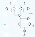
The goal of this exercise is to study the effects of a modified differential amplifier that reduces the bias current that's shown in the attached image. The first part of the exercise is to calculate by how much the bias current is reduced with the addition of the Q7-Q8 pair. I found this current to be
\(I_B = \frac{2\beta+1}{(\beta+1)^3}\.\times\.\frac{I}{2}\)
which results in a reduction of
\( \frac{2\beta+1}{(\beta+1)^2}\approx\frac{2}{\beta}\)
Next I'm asked to calculate by how much the input resistance changed, which I expected to be by a factor of \(\frac{\beta}{2}\), but looking at the circuit, it seems that the input resistance \(R_{ib}=2r_{\pi}\) is in parallel with the output resistance of the current mirror, which is much larger. Thus, I concluded that the input resistance was unchanged, so \(R_{ib}\approx2r_{\pi}\). This contradicted what I expected, so I decided to do some quick small signal analysis and found
\(i_i = \frac{\beta^3+2\beta^2+\beta^3+1}{\beta^3+2\beta^2+\beta^3+2}i_{b1}\approx i_{b1}\)
Which leads to the same conclusion regarding the input resistance. So my question is, are these two approaches wrong, or am I wrong in assuming that the input resistance should increase just because it draws less current.
I did some simulations and the input resistance did increase, but since I'm not very good at using SPICE, I might have screwed something up.
Attachments
-
 69 KB Views: 4


