Science Olympiad Practice Challenge #1

Thread Starter

WBahn

Joined Mar 31, 2012
33,309
I'm coaching a Science Olympiad Circuit Lab team (both Division B (middle school) and Division C (high school)). As part of this, I'm coming up with little challenges comparable to what they might see at a tournament related to what I am teaching them at the time. I'll post some of them here in case folks are interested in trying them. I'm also open to thoughts and suggestions.

We've just gotten started, so they are learning about voltage sources and resistors and Ohm's Law, KCL, and KVL. As part of this, I'm also introducing them to the difference between ideal and real world measurements and instruments. This is the challenge I came up with to drive that home:

--------------------------------------------------------
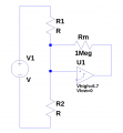
The following circuit is provided to you:
1792090060076.png

You are also provided with a voltmeter that has an input resistance, RM, of 1 MΩ.

Using this meter, you are to determine the values of R1 and R2. You may not modify the circuit. You may only make voltage measurements, using the provided meter, across the labeled nodes (i.e., you can measure Vab, Vbc, and/or Vac).

The two resistors are 5% tolerance resistors whose values are in the E12 set of preferred values.

What are the colors of the bands on each resistor, left to right, with the tolerance band on the right?
--------------------------------------------------------

Here are the three measurement so that everyone has the same data to work with:

Vab = 3.12 V
Vbc = 317 mV
Vac = 6.70 V

Please limit yourselves to the same conditions that the teams would face, namely that they have a basic scientific calculator and pencil/paper. They can also bring a binder with whatever reference material they want, but it is unlikely that they would have anything in it that would directly help them with this problem.

Out of curiosity, I fed this problem to three LLMs (only asked them to find R1 and R2, not determine what the nominal resistance was) and half of them got it wrong.

ChatGPT: 484 kΩ, 22.5 kΩ (it gave a very detailed derivation of how it arrived at these values, which sounded very reasonable and addressed the key issues)
Gemini: 500 kΩ, 47 kΩ (it claimed that these were the nearest standard values, even though I didn't ask for that).
Perplexity: 48.7 kΩ, 1.05 MΩ
Copilot got the correct values, but it did so through an iterative approach.
Grok and DeepSeek got the correct values, but didn't indicate how it got them.
Claude: Didn't respond.
 

Attachments

Ian0

Joined Aug 7, 2020
13,306
Did you notice that it was exactly the same calculations as if you wanted to design a comparator with trigger points of 3.12V and 317mV?Screenshot from 2026-10-16 08-29-24.png
 
Last edited:

Ya’akov

Joined Jan 27, 2019
10,345
Out of curiosity, I fed this problem to three LLMs
I gave the problem to ChatGPT's Astra—the latest and much improved model. This is the result...

R1: brown–black–blue–gold (10 MΩ, ±5%)
R2: brown–black–green–gold (1 MΩ, ±5%)


The trick is that the meter significantly loads the circuit. The two resistor readings are taken under different circuit conditions, so they need not add up to 6.70 V.

Assume the source is ideal and stable, as drawn:
\[
V_s = V_{ac} = 6.70\,\mathrm{V}.
\]
When measuring across R1, the meter is in parallel with it. The current through R2 supplies both:

\[
\frac{V_s-V_{ab}}{R_2}
=
\frac{V_{ab}}{R_1}
+
\frac{V_{ab}}{R_M}.
\]

Similarly, when measuring across R2:

\[
\frac{V_s-V_{bc}}{R_1}
=
\frac{V_{bc}}{R_2}
+
\frac{V_{bc}}{R_M}.
\]

Multiplying both equations by R1R2, then dividing by their respective measured voltages, gives:

\[
\left(\frac{V_s}{V_{ab}}-1\right)R_1
=
R_2+\frac{R_1R_2}{R_M},
\]

\[
\left(\frac{V_s}{V_{bc}}-1\right)R_2
=
R_1+\frac{R_1R_2}{R_M}.
\]

Subtracting cancels the product term. Rearranging yields:

\[
\frac{R_1}{R_2}=\frac{V_{ab}}{V_{bc}}.
\]

Substitution gives:

\[
R_1=R_M\frac{V_s-V_{ab}-V_{bc}}{V_{bc}},
\qquad
R_2=R_M\frac{V_s-V_{ab}-V_{bc}}{V_{ab}}.
\]

The common numerator is:

\[
6.70-3.12-0.317=3.263\,\mathrm{V}.
\]

With a meter resistance of 1 MΩ:

\[
R_1=(1\,\mathrm{M}\Omega)\frac{3.263}{0.317}
\approx 10.293\,\mathrm{M}\Omega,
\]

\[
R_2=(1\,\mathrm{M}\Omega)\frac{3.263}{3.12}
\approx 1.0458\,\mathrm{M}\Omega.
\]

These are respectively 2.93% above 10 MΩ and 4.58% above 1 MΩ. Both are within 5%, identifying the E12 nominal values.

With the gold tolerance band on the right:
  • R1: brown–black–blue–gold — 10 × 10⁶ Ω, ±5%.
  • R2: brown–black–green–gold — 10 × 10⁵ Ω, ±5%.
 

Thread Starter

WBahn

Joined Mar 31, 2012
33,309
I gave the problem to ChatGPT's Astra—the latest and much improved model. This is the result...

R1: brown–black–blue–gold (10 MΩ, ±5%)
R2: brown–black–green–gold (1 MΩ, ±5%)


The trick is that the meter significantly loads the circuit. The two resistor readings are taken under different circuit conditions, so they need not add up to 6.70 V.

Assume the source is ideal and stable, as drawn:
\[
V_s = V_{ac} = 6.70\,\mathrm{V}.
\]
When measuring across R1, the meter is in parallel with it. The current through R2 supplies both:

\[
\frac{V_s-V_{ab}}{R_2}
=
\frac{V_{ab}}{R_1}
+
\frac{V_{ab}}{R_M}.
\]

Similarly, when measuring across R2:

\[
\frac{V_s-V_{bc}}{R_1}
=
\frac{V_{bc}}{R_2}
+
\frac{V_{bc}}{R_M}.
\]

Multiplying both equations by R1R2, then dividing by their respective measured voltages, gives:

\[
\left(\frac{V_s}{V_{ab}}-1\right)R_1
=
R_2+\frac{R_1R_2}{R_M},
\]

\[
\left(\frac{V_s}{V_{bc}}-1\right)R_2
=
R_1+\frac{R_1R_2}{R_M}.
\]

Subtracting cancels the product term. Rearranging yields:

\[
\frac{R_1}{R_2}=\frac{V_{ab}}{V_{bc}}.
\]

Substitution gives:

\[
R_1=R_M\frac{V_s-V_{ab}-V_{bc}}{V_{bc}},
\qquad
R_2=R_M\frac{V_s-V_{ab}-V_{bc}}{V_{ab}}.
\]

The common numerator is:

\[
6.70-3.12-0.317=3.263\,\mathrm{V}.
\]

With a meter resistance of 1 MΩ:

\[
R_1=(1\,\mathrm{M}\Omega)\frac{3.263}{0.317}
\approx 10.293\,\mathrm{M}\Omega,
\]

\[
R_2=(1\,\mathrm{M}\Omega)\frac{3.263}{3.12}
\approx 1.0458\,\mathrm{M}\Omega.
\]

These are respectively 2.93% above 10 MΩ and 4.58% above 1 MΩ. Both are within 5%, identifying the E12 nominal values.

With the gold tolerance band on the right:
  • R1: brown–black–blue–gold — 10 × 10⁶ Ω, ±5%.
  • R2: brown–black–green–gold — 10 × 10⁵ Ω, ±5%.
Except the Science Olympiad teams don't get to let ChatGPT's Astra do their thinking for them.
 

Thread Starter

WBahn

Joined Mar 31, 2012
33,309
Did you notice that it was exactly the same calculations as if you wanted to design a comparator with trigger points of 3.12V and 317mV?View attachment 372314
No, I hadn't noticed that, but that is certainly a very good observation, though I don't know that it makes the math any easier. It's certainly not something I would expect an SO team, particularly a middle school team, to recognize or utilize.
 

MrChips

Joined Oct 2, 2009
35,268
R1 = 10 MΩ
R2 = 1 MΩ
I used more logic than math.

1) Because Vab is about 10 times higher than Vbc, I assumed that R1 must be large and R2 must be relatively small.

2) Since Vab is about 50% of Vac, R2 must be about the same resistance as the meter resistance. Hence R2 is about 1 MΩ.

3) Going back to step (1) and a little bit of math puts R1 = 10 MΩ.

4) I did not consider 5% resistance tolerance.
 

Thread Starter

WBahn

Joined Mar 31, 2012
33,309
I used more logic than math.

1) Because Vab is about 10 times higher than Vbc, I assumed that R1 must be large and R2 must be relatively small.

2) Since Vab is about 50% of Vac, R2 must be about the same resistance as the meter resistance. Hence R2 is about 1 MΩ.

3) Going back to step (1) and a little bit of math puts R1 = 10 MΩ.

4) I did not consider 5% resistance tolerance.
Although the reasoning seems pretty good qualitatively, it probably lucked out because I happened to choose "nice-valued" 1 MΩ and 10 MΩ resistors. If I had chosen, say, 1.2 MΩ and 12 MΩ, I don't know if that would have changed your answers.
 

Thread Starter

WBahn

Joined Mar 31, 2012
33,309
The first pair of resistors I used to get the actual measurements were, nominally, 1 MΩ and 10 MΩ. The voltages that I got led to a result that the 10 MΩ resistor was 10.85 MΩ, which is well above a 5% tolerance. At first, I assumed that this was because I was intentionally using a $5 DMM and that it's actual input resistance might be well off of the claimed 1 MΩ, not to mention possibly not meeting the claimed accuracy in the documentation. So I pulled out my Fluke 27, which measures up to 30 MΩ, and it said the resistance was 10.85 MΩ. The fact that these resistors were originally purchased at Radio Shack about four decades ago and have never been properly stored may account for the out of tolerance value. That, in and of itself, was a good point to discover. If I were to use this as an actual tournament exercise, I better make sure that all of the components I'm using actually meet the relevant specs. That's what I did to get the values in the problem posted here. The values, as measured by the Fluke 27, were R1 = 10.22 MΩ and R2 = 1.040 MΩ.
 

Thread Starter

WBahn

Joined Mar 31, 2012
33,309
SOLUTION (Not the only possible way to go about it, though).

The solution I came up with is pretty much identical to one provided by Astra in Post $3 above, but exploited symmetry explicitly.

This derivation should hopefully be detailed enough for everyone, including any SO teams that come across it, to follow'

NOTE: I can't enclose this in SPOILER tags because the equations won't render. So skip this post if you don't want to see the solution yet.

\(
V_{ab} \; = \; V_s · \frac{\left(R_1||R_M\right)}{\left(R_1||R_M\right) \; + \; R_2}
\)
Solve for R_2:

\(
\left( R_1||R_M \right) \; + \; R_2 \; = \; \frac{V_s}{V_{ab}} · R_1||R_M \\
R_2 \; = \; \frac{V_s}{V_{ab}} · R_1||R_M \; - \; R_1||R_M \\
R_2 \; = \; \left( \frac{V_s}{V_{ab}} \; - \; 1 \right) · R_1||R_M \\
R_2 \; = \; \left( \frac{V_s}{V_{ab}} \; - \; 1 \right) · \frac{R_1·R_M}{R_1\; + \;R_M}
\)
Multiply both sides by the denominator:

\(
\left( R_1\; + \;R_M \right) · R_2 \; = \; \left( \frac{V_s}{V_{ab}} \; - \; 1 \right) · R_1 · R_M \\
R_1 · R_2 \; + \; R_M · R_2 \; = \; \left( \frac{V_s}{V_{ab}} \; - \; 1 \right) · R_1 · R_M
\)
By symmetry:

\(
R_1 · R_2 \; + \; R_M · R_1 \; = \; \left( \frac{V_s}{V_{bc}} \; - \; 1 \right) · R_2 · R_M
\)
Subtract the last equation from the prior equation:

\(
R_M · R_2 \; - \; R_M · R_1\; = \; \left( \frac{V_s}{V_{ab}} \; - \; 1 \right) · R_1 · R_M \; - \left( \frac{V_s}{V_{bc}} \; - \; 1 \right) · R_2 · R_M \\
R_2 \; - \; R_1\; = \; \left( \frac{V_s}{V_{ab}} \; - \; 1 \right) · R_1 \; - \left( \frac{V_s}{V_{bc}} \; - \; 1 \right) · R_2 \\
R_2 \; - \; R_1\; = \; \left( \frac{V_s}{V_{ab}} R_1 \; - \; R_1 \right) \; - \left( \frac{V_s}{V_{bc}} R_2 \; - \; R_2 \right) \\
R_2 \; - \; R_1\; = \; \frac{V_s}{V_{ab}} R_1 \; - \frac{V_s}{V_{bc}} R_2 \; + \; R_2 \; - \; R1 \\
0 = \; \frac{V_s}{V_{ab}} R_1 \; - \frac{V_s}{V_{bc}} R_2 \\
\frac{V_s}{V_{ab}} R_1 \; = \; \frac{V_s}{V_{bc}} R_2
\)
Solve for the ratio R_2/R1:

\(
\frac{R_2}{R_1} \; = \; \frac{V_{bc}}{V_{ab}}
\)

This, to me, was a pretty surprising and quite non-intuitive result. Regardless of the meter's resistance and despite the fact that it is resulting in to different circuits for the respective measurements, the ratio of the measured voltages across the two resistors remains that same as when the meter isn't there (or is ideal). In fact, when I got it, I suspected I had done something wrong in the math.

With this result, we can go back to an earlier equation and rearrange it in terns of R_2/R_1:

\(
R_1 · R_2 \; + \; R_M · R_2 \; = \; \left( \frac{V_s}{V_{ab}} \; - \; 1 \right) · R_1 · R_M \\
R_2 \; + \; R_M · \frac{R_2}{R_1} \; = \; \left( \frac{V_s}{V_{ab}} \; - \; 1 \right) · R_M \\
R_2 \; + \; R_M · \frac{V_{bc}}{V_{ab}} \; = \; \left( \frac{V_s}{V_{ab}} \; - \; 1 \right) · R_M \\
R_2 \; = \; \left( \frac{V_s}{V_{ab}} \; - \; 1 \right) · R_M \; - \; R_M · \frac{V_{bc}}{V_{ab}} \\
R_2 \; = \; R_M · \left( \left( \frac{V_s}{V_{ab}} \; - \; 1 \right) \; - \; \frac{V_{bc}}{V_{ab}} \right) \\
R_2 \; = \; R_M · \left( \frac{V_s}{V_{ab}} \; - \; \frac{V_{ab}}{V_{ab}} \; - \; \frac{V_{bc}}{V_{ab}} \right) \\
R_2 \; = \; R_M · \frac{V_s \; - \; \left(V_{ab} \; + \; V_{bc} \right)}{V_{ab}}
\)
By symmetry:

\(
R_1 \; = \; R_M · \frac{V_s \; - \; \left(V_{ab} \; + \; V_{bc} \right)}{V_{bc}}
\)

Of course, once you have one of the resistors, you can use the ratio of the two voltages to find the other. Or, you can note that the only difference between the two equations above is the denominator in the fraction, so you can save the result of everything else and just divide by the new denominator.

Using the given values in the first post:

Vab = 3.12 V
Vbc = 317 mV
Vac = 6.70 V

We get:
R1 = 1.046 MΩ (which is 1 MΩ + 4.6%)
R2 = 10.29 MΩ (which is 10 MΩ + 2.9%)

So the two resistors and their markings are:
R1: 1 MΩ brown-black-green-gold
R2: 10 MΩ brown-black-blue-gold

When I measured these resistors with my Fluke 27, they read as R1 = 1.040 MΩ and R2 = 10.22 MΩ. Relative to the Fluke's readings, the calculated R1 was 0.58% high and R2 was 0.68% high. Thus the results were an average of about 0.6% high, which could be due to the $5 meter having a slightly lower input resistance than 1 MΩ, the voltmeter having a slight error, or the Fluke having an error in the ohmmeter readings (or some combination).

The Fluke's accuracy on the 32 MΩ range is ±(1% + 1 digit) which puts

R1 = 1.040 MΩ ± 11.4 kΩ (1.029 MΩ to 1.051 MΩ)
R2 = 10.22 MΩ ± 103.2 kΩ (10.22 MΩ to 10.32 MΩ)

This is assuming that this 30+ year old meter is still in spec.

So the entire discrepancy could be due to just the Fluke. Or, any single other item even if it's in spec.
 
Last edited:
Thread starter Similar threads Forum Replies Date
WBahn General Science, Physics & Math 9
Top