[S.T. - 9] JFETs and MOSFETs analysis

Thread Starter

PsySc0rpi0n

Joined Mar 4, 2014
1,772
I'm startting my next task which is to analyse JFETs and MOSFETs.

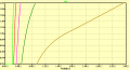
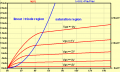
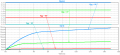
Our tutor is asking us to calculate Rds "ON" from Id(Vds) curves. How do we do this "correctly" from the attached plot?

Is this resistance calculated for Vgs = 0V and at it's max current???
 

Attachments

Last edited:

Thread Starter

PsySc0rpi0n

Joined Mar 4, 2014
1,772
Hi. Good morning.

I need some help here, please, someone!

I've been told that rDS "ON" is only calculated for the linear/triode region and that there is no other region where rDS in "ON". How do I correctly calculate this resistance?
 

Thread Starter

PsySc0rpi0n

Joined Mar 4, 2014
1,772
Morning...

While trying to simulate the attached circuit to calculate rDS "ON", why does the light blue curve has that weird straight line?

If I turn Vgg upside down and change the swipe values from -6V to 0V to 0V to 6V, the plot looks correct, but I think it's not the correct way...

Can anyone help me figure this out?
 

Attachments

ericgibbs

Joined Jan 29, 2010
18,864
hi psy.
I do not get a straight blue line on my sim.
E
OT: I have relatives from South Africa here for a few weeks, so I will not be around as usual.;)
 

Attachments

Thread Starter

PsySc0rpi0n

Joined Mar 4, 2014
1,772
Sure, family first!

You don't have a weird blue straight line as mine but you also have a weird green line next to Y-axis! Where does it comes from?
 

Jony130

Joined Feb 17, 2009
5,488
VBB should never be larger than +0.6V. Also if you want to find rsd(on) Vds must be lower then (Vgs - Vp). In your example Vdd<2V
 

Attachments

Last edited:

Thread Starter

PsySc0rpi0n

Joined Mar 4, 2014
1,772
VBB should never be larger than +0.6V. Also if you want to find rsd(on) Vds must be lower then (Vgs - Vp). In your example Vdd<2V
Jony130, your plots look really great... But can you explain what is each one? And how do you find the values to plot the linear/triode curve??? You say that Vbb should never be larger than +0.6V. Where is Vbb??? Did you meant Vgg? And when you say that Vds must be lower than Vgs - Vp is to ensure that the mosfet is in the saturation region? And how do you manage to use the symbol Omega itself in your plots?
 

Thread Starter

PsySc0rpi0n

Joined Mar 4, 2014
1,772
Well, I need to move on...

My tutor is asking us to simulate the attached circuit and to use the following youtube link to implement the switch that is in the circuit. But probably I haven't adapted the youtube link instructions correctly to the circuit...

Youtube Link

The circuit I tried to simulate is also attached. Please help me. I have a few specific questions to answer that I just don't have a clue!
 

Attachments

ericgibbs

Joined Jan 29, 2010
18,864
hi psy,
Always try to layout the LTS sim circuit the same as the test circuit.
Look at this option.
You should fully define the Pulse parameters.
E
 

Attachments

Thread Starter

PsySc0rpi0n

Joined Mar 4, 2014
1,772
hi psy,
Always try to layout the LTS sim circuit the same as the test circuit.
Look at this option.
You should fully define the Pulse parameters.
E
Morning Mr. EricGibbs

Thanks a lot for the correct sim.

My teacher is asking a few specific questions that I have no idea how to answer. I hope you can ive me a few hints on how to answer them. I have to deliver this report tonight before 9:00pm.

1 - He says that that circuit is an electronic timer circuit and he asks if the switch is pressed for a few milliseconds, what is the achieved timing??? He also asks how could we use this circuit to measure the capacitor value. These 2 questions are part of the first question.

2 - Then the second question is if we could use a BJT instead of a MOSFET to the same purposes!

3 - The last question is also split into two. They are: Could we use this circuit to control a 12V DC engine? If not, what we should change to be able to do so???

Can you help me answering with some hints for each one?
 

ericgibbs

Joined Jan 29, 2010
18,864
1 - He says that that circuit is an electronic timer circuit and he asks if the switch is pressed for a few milliseconds, what is the achieved timing??? He also asks how could we use this circuit to measure the capacitor value. These 2 questions are part of the first question.

You need to calc the C1 charge time and voltage via RG1, then the discharge time of C1 via RG2 using the charged voltage.

2 - Then the second question is if we could use a BJT instead of a MOSFET to the same purposes!
Consider/compare the input impedance of a FET versus a BJT anf think how this would effect the Charge /discharge times.

3 - The last question is also split into two. They are: Could we use this circuit to control a 12V DC engine? If not, what we should change to be able to do so???
Consider the effect of using an inductive load [ motor] versus a resistive load and the required back emf protection,,,etc.

Hope these clues help you answer the questions.
Use the standard formula's for charge/discharge times.
E
 
Top