
Running small 110V motor on 220V

Status
Not open for further replies.

7PAGESIN

Joined Feb 8, 2012
1
For what it's worth, I used to know a very knowledgeable chap at work, who swore by putting a diode in series with a drill for instance, to effect a dual speed function. If memory serves he recommended a BY127, but whether this will work with an induction motor I would wonder; I would think that it's not just a case of cutting the voltage in half.

For what it's worth, I used to know a very knowledgeable chap at work, who swore by putting a diode in series with a drill for instance, to effect a dual speed function. If memory serves he recommended a BY127, but whether this will work with an induction motor I would wonder; I would think that it's not just a case of cutting the voltage in half.
 

MisterBill2

Joined Jan 23, 2018
27,888
The diode will work with a universal, (series brush type) motor fairly well, BUT it will probably not work with an induction motor at all.The induction motor is effectively a transformer with a rotating secondary, and transformers depend on the constant changing and reversal of the magnetic field to function.
And on one occasion when an unknowing fool plugged a 120 volt shop vac (universal motor type), into a 240 volt cord, the operation was very loud for almost a minute, until the universal motor filed and ignited. The cord was well marked as 240 volts, the big tag was ignored.
 

Tonyr1084

Joined Sep 24, 2015
9,744
Induction occurs every time the polarity changes. DC doesn't change polarity. And with an AC signal and a blocking diode, you will get pulsed DC but the polarity will never change. The motor shouldn't run at all.
 

Danko

Joined Nov 22, 2017
2,204
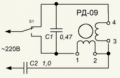
Put capacitor in series with motor.
Begin with small, about 0.1uF.
Measure voltage on motor, if it is lower than 110V,
then increase capacitance.
So, step by step, appropriate capacitance will selected.
For example:
Standard 127V single phase reversible servo motor
connected to 220V line through ballast capacitor C2:
1638300049973.png
 
Last edited:

MisterBill2

Joined Jan 23, 2018
27,888
Put capacitor in series with motor.
Begin with small, about 0.1uF.
Measure voltage on motor, if it is lower than 110V,
then increase capacitance.
So, step by step, appropriate capacitance will selected.
Unless that capacitor is a "perfect " capacitor there will be some losses that result in heat being produced in the capacitor. That is the unfortunate downside of using a capacitor. So a physically larger capacitor will be the better choice, no matter what the capacitance value. Another potential source of grief is any distortion in the power. Distortion shows up as higher frequency components and they are passed on with less dropping in their voltage. It is quite possible to either have the series capacitor melt or break down if it is not able to handle the power dissipated in the various losses.
 

PBates123

Joined Apr 9, 2010
2
I have a liquid cooled CNC machine that runs on 220V/60Hz. The cooling pump, which is an aquarium/fountain pump, is 110V/60Hz. Presently, I have to plug the cooling pump in separately, which recently lead to a situation where I ran without cooling for a few minutes. No big deal, but I want to prevent this from happening again by connecting the cooling pump to the main, 220V circuit so it comes on as I power on the machine itself.

Unfortunately, neither the machine's power cord nor the wiring in my walls have a neutral wire. I suppose I could get 110V by using the ground, but that seems like a terrible, possibly dangerous idea.

This is the pump - https://www.amazon.com/gp/product/B077S2TCT2. I bought this one because it's from a European company, made in Europe, and the Amazon picture showed a European electrical tag (220V/50Hz). I was hoping for a European unit with a US plug, but the unit I got has a tag that says 120V/60Hz.

The motor itself, or the stator at least, is completed epoxy potted. The only moving part is a rotor with a magnet that looks like this - https://www.amazon.com/Magnetic-Replacement-Assembly-Aquarium-Impeller/dp/B01E6V649Y, which sits in a blind hole on the "exposed to water" side of the pump (obviously ;-).

As you can tell, I don't know much about motors. Part of me thinks the part is universal and the manufacturer just labels it with US or Global power specs, and that I'd be fine to try hooking it up to 220V/60Hz. On the other hand, if that were the case, why not just put a universal label on it, too?

My questions are two:

1. Based on this limited info, what's the likelihood the pump catches fire and melts if I connect it to 220V, wasting my $45?
2. If it doesn't melt, at least initially, do you think I'm impacting it's longevity by running it on 220V?

I get confused with electricity. Part of me thinks it might run faster on 220V. Part of me thinks the speed will be the same because of the 60Hz being the same, and it will just pull fewer amps on 220V, like some of my power tools that can be wired either way. And part of me thinks the 220V is too much "pressure" for a coil potentially designed for 110V, and the whole think will heat up and grenade. All of these seem like viable ideas, I just get confused about how they interact with each other and which ideas apply to which motor types.

Any help is appreciated. Thanks!
Check this out. Unfortunately it will cost almost as much as the pump.....
https://www.amazon.com/Pyle-voltage...locphy=9032152&hvtargid=pla-351511913275&th=1
 

MisterBill2

Joined Jan 23, 2018
27,888
In post #16 the TS comments that they located and purchased a pump that will work with the 220, and returned the 120 volt pump. And nobody would put different labels on a lower voltage pump to imply that it would be OK with the higher voltage, because it will not be OK.
AND if it were an installation in the US with 2 hot legs and the neutral missing, finding a neutral wire in most houses is not such a challenge. Now in the UK, where the single pair voltage is 220, one side neutral, the situation is different.
 

mmcginty

Joined Feb 4, 2010
57
Because it is intended for safety purposes only, not to be used as a circuit conductor. ;)
In the question he states:

>> neither the machine's power cord nor the wiring in my walls have a neutral wire. <<

If that is indeed the case (which I find hard to imagine) how could the machine work without using ground as part of the circuit? There has to be a return or else it's an open circuit. There may not be a white wire but there has to be a neutral. Test voltage from each wire to ground, the one that reads zero volts is the neutral. (The same exercise should lead you to a source of 110V.)

(It's also significant to note that, for buildings without a grounding rod, ground and neutral are tied to the same lug in the breaker panel.)
 

mmcginty

Joined Feb 4, 2010
57
[...]
Unfortunately, neither the machine's power cord nor the wiring in my walls have a neutral wire. I suppose I could get 110V by using the ground, but that seems like a terrible, possibly dangerous idea.
[...]
There may not be a white wire but one of them has to be neutral, otherwise it would be an open circuit, there has to be a return. Use a volt meter to measure voltage between each wire and ground, the one that reads 0 volts is neutral (and you can use it and one of the other wires to get 110V.)
 

Tonyr1084

Joined Sep 24, 2015
9,744
I just installed a 220V table saw. It has 10/2 conductors. That is it has a 10 gauge black wire and a 10 gauge white wire. As with any currently available wire, a 10/2 also has a ground wire. The ground wire is there to provide a safe path to ground should one of the two live lines come in contact with the case. You don't "Need" a "Neutral" wire in a 220 V setup.

Looking back on the installation I wish I would have done a 10/3 setup. Then I would have a "Neutral" available so I could pick 110V. With a 30 amp breaker powering the saw I would need an additional 15 amp breaker at the 110V setup so I could protect the wiring properly. However, just using one leg of the 220V and the ground, while it will work, is foolish and dangerous. Also, it's a violation of code. It's a violation because it's not safe. Someone could die. Safety is a HUGE factor in all electrical and electronic circuit design. How do you keep a fool safe? That can be a tricky matter because the fool will try to circumvent the safety precautions only to become a swift memory of who that fool was.
There may not be a white wire but one of them has to be neutral, otherwise it would be an open circuit, there has to be a return.
That's not true. In standard US House wiring, there is split phase 240VAC entering the house. Splitting that 240 is a Neutral. Therefore you get 120VAC between either leg and neutral, but the full 240 between both legs. It's been that way for many years. Other countries likely have different wiring setups - setups which I'm not familiar with, nor qualified to discuss. Unless the discussion is for me to learn something I didn't previously know.

Open your circuit panel and measure the voltage from any single breaker and neutral and you'll find 110V. Measure between any two adjacent breakers and you will find 220V. Then close up the panel to prevent anyone from accidentally poking a finger at a circuit and getting a charge out of it.
 

MisterBill2

Joined Jan 23, 2018
27,888
In the question he states:

>> neither the machine's power cord nor the wiring in my walls have a neutral wire. <<

If that is indeed the case (which I find hard to imagine) how could the machine work without using ground as part of the circuit? There has to be a return or else it's an open circuit. There may not be a white wire but there has to be a neutral. Test voltage from each wire to ground, the one that reads zero volts is the neutral. (The same exercise should lead you to a source of 110V.)

(It's also significant to note that, for buildings without a grounding rod, ground and neutral are tied to the same lug in the breaker panel.)
In the US, a machine requiring 240 volts can function quite well with the two hot wires providing 240 AC between them. My central air compressor functions quite well with no neutral connection, only Black, Red, and a bare green wire ground connection.
Likewise, 480 volt 3-phase motors have no provision for a neutral connection, only the three phases and the safety ground. It does get very inconvenient when a neutral is required for some system addition and none is available. And cost-cutters often leave out that neutral wire if the initial application does not demand it.
 

MaxHeadRoom

Joined Jul 18, 2013
30,758
There may not be a white wire but one of them has to be neutral, otherwise it would be an open circuit, there has to be a return. Use a volt meter to measure voltage between each wire and ground, the one that reads 0 volts is neutral (and you can use it and one of the other wires to get 110V.)
Another example is when transformers are used in commercial enclosures to provide 120v for control, neither of the secondary conductors is a neutral.
But what is allowed, and often done, is to reference one side of the secondary to the earth ground conductor, this conductor then becomes a Neutral, either way it works. ;)
 

MisterBill2

Joined Jan 23, 2018
27,888
There is NO ELECTRICAL reason why a "return wire" has to be a neutral (grounded) wire. That is a convention, originally used to save wire and effort. In some instances it also makes using the system safer.
But a whole path circuit does not require that any of the conductors be at "zero potential" relative to ground. Circuit requirements and common practice are two completely different things.
 
Status
Not open for further replies.
Top





