Facebook
 Google
 GitHub
 Linkedin
TLDR: Diagnostic method guidance sought for magnet + coil triggered triac speed controller circuit. Clueless Mechanical Engineer needs coaching.
A friend gave me an old food mixer to fix. She said it smokes and smells.
I am a mechanical engineer by profession and pride myself that I can fix anything .... eventually ... but this one is stumping me so I thought I'd ask for help from the forum. Also, I'd like to learn more about this type of stuff.
There is a movable controller board, with two pins, whose proximity to a rotating magnet on a brushed ac motor varies when you turn the speed dial. The whole board tilt so the pins get closer to the rorating magnet. I think this triggers a diac-triac which chops the sine wave.
This sounds crude .... but my 2019 Kitchen Aid uses a Watt Governor, like a steam engine, so this is high tech in Mixerland!!
When I plugged it in it worked apart from a graunching from the gearbox and the aforementioned smell.
I fixed the 'box and pulled the board. There were some dead looking capacitors so I replaced all the big caps. I also replaced the triac and a high power resistor which looked toasted.
I reassembled it and it no longer smells but I've lost speed control.
ARGH!
I pulled one leg of each cap and resistor and double checked they are right capacitance/resistance. All OK and same as numbers / codes on old parts.
I checked all continuities. All OK.
I could not test the new triac but I assume it is OK.
I think I need to put a scope on it and figure out what is going on but I have no clue really - I'm a mechanical engineer.
I tried a scope across the thru hole winding which I think is supposed to sense the flux from the pins pointing at the rotating magnet but all I got is a mess. The winding is 39 ohms so that seems sensible and the pins appear to connect to a core thru the winding as a kind of flux supplying core. The two pins are electrically continuous, so I assume there is no break in the flux path. So why is the coil signal a mess? Do I need to disconnect one end of coil to make sure the problem is not from elsewhere? No idea.
*** I'm looking for general rules on how you trouble shoot a circuit like this. I'm pretty clueless and I'd be very grateful ***
Do I start at the triac and work back? Or start at the coil and work forwards?
I'm guessing the coil waveform should be at rotational frequency and weak ... weaker as it moves away from the magnet.
There is a little transistor and a bunch of diodes which I guess are there to "perk up" and "square up" the coil signal before it reaches the diac-triac.
I'm guessing that the triac output should be a sort of chopped up ac mains wave.
But I am unsure of this and have no clue what the intermediate wave forms should be, or even whether the 'scope is the right diagnostic tool.
Thanks for any advice.
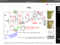
I have a circuit diagram from another model which I think is correct for this one, too.
A friend gave me an old food mixer to fix. She said it smokes and smells.
I am a mechanical engineer by profession and pride myself that I can fix anything .... eventually ... but this one is stumping me so I thought I'd ask for help from the forum. Also, I'd like to learn more about this type of stuff.
There is a movable controller board, with two pins, whose proximity to a rotating magnet on a brushed ac motor varies when you turn the speed dial. The whole board tilt so the pins get closer to the rorating magnet. I think this triggers a diac-triac which chops the sine wave.
This sounds crude .... but my 2019 Kitchen Aid uses a Watt Governor, like a steam engine, so this is high tech in Mixerland!!
When I plugged it in it worked apart from a graunching from the gearbox and the aforementioned smell.
I fixed the 'box and pulled the board. There were some dead looking capacitors so I replaced all the big caps. I also replaced the triac and a high power resistor which looked toasted.
I reassembled it and it no longer smells but I've lost speed control.
ARGH!
I pulled one leg of each cap and resistor and double checked they are right capacitance/resistance. All OK and same as numbers / codes on old parts.
I checked all continuities. All OK.
I could not test the new triac but I assume it is OK.
I think I need to put a scope on it and figure out what is going on but I have no clue really - I'm a mechanical engineer.
I tried a scope across the thru hole winding which I think is supposed to sense the flux from the pins pointing at the rotating magnet but all I got is a mess. The winding is 39 ohms so that seems sensible and the pins appear to connect to a core thru the winding as a kind of flux supplying core. The two pins are electrically continuous, so I assume there is no break in the flux path. So why is the coil signal a mess? Do I need to disconnect one end of coil to make sure the problem is not from elsewhere? No idea.
*** I'm looking for general rules on how you trouble shoot a circuit like this. I'm pretty clueless and I'd be very grateful ***
Do I start at the triac and work back? Or start at the coil and work forwards?
I'm guessing the coil waveform should be at rotational frequency and weak ... weaker as it moves away from the magnet.
There is a little transistor and a bunch of diodes which I guess are there to "perk up" and "square up" the coil signal before it reaches the diac-triac.
I'm guessing that the triac output should be a sort of chopped up ac mains wave.
But I am unsure of this and have no clue what the intermediate wave forms should be, or even whether the 'scope is the right diagnostic tool.
Thanks for any advice.
I have a circuit diagram from another model which I think is correct for this one, too.