 Facebook
 Google
 GitHub
 Linkedin
Hi all
I'm looking for help with a circuit.

Source: http://samplethemartian.blogspot.com/2015/04/rock-band-drums-use-real-kick-pedal.html
My Background:
I have a background in computer engineering but concentrated on software engineering. I took quite a few circuits, electronics, digital design and embedded systems classes in college but that was almost 10 years ago.
Project:
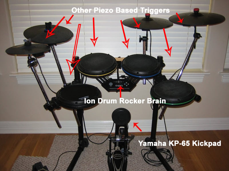
My current project involves connecting a piezo based drum (Yamaha KP65) to my Ion Drum Rocker electronic drum set. The KP65 offers a more realistic experience as it requires you actually use a real bass pedal and beater. It can also be used along with a double bass pedal required for some styles of music.
The Problem:
The Ion Drum Rocker brain expects an active low trigger on it's bass input while the kickdrum delivers a pretty low and noisy momentary voltage when triggered. The stock trigger witch comes with the set uses some type of magnetic switch pull the signal low.
Interestingly enough all of the other inputs to the Ion Drum Rocker Brain take in piezo based signals. I'm able to plug the KP65 into the other inputs and trigger them correctly.
The Solution:
The optimal solution would be pretty inexpensive and able to accurately trigger the brain very quickly with no cross talk or mis-triggers. If you're familiar with Rock Band some drum parts require 16th notes played at very high beats per minute. So something like 5-10 triggers per second.
I've researched this problem for a while now and come across a few of solutions. There used to be a product called the "Kickbox" (~$30-50) which converted the piezo based signal for use with the drum controller. The manufacturer has gone out of business but a few people have worked to reverse engineer it's functionality. Above is a schematic of a circuit designed and refined by a number of DIYer's about 5 years ago.
My Understanding of the circuit:
The LM 386 Amp takes in the signal from the piezo and amplifies it. I believe the LM 386 automatically biases it's output to 1/2 the input voltage (2.5v).
This is then passed into the 555 timer which amplifies and cleans the signal from the LM 386 to something that can bias the 2N3904 BJT such that it pulls down the signal going to the brain to trigger the bass note in game. The Pot in the upper left is for fine tuning
I've implemented this on a breadboard with medium success. I was able to get the kickdrum to trigger successfully but occasionally when triggered the out put of the BJT would stay low and not come back up to 3v so no subsequent triggers would register. The only way to stop this has been to power cycle the circuit.
I like this design because it uses cheap components I have on hand. I've seen other circuits with multiple Op Amps that utilize dozens of resistors and 3+ DIP IC's.
Questions:
1. Is this the most viable solution?
2. Any idea why the output occasionally goes down to 0v and stays there instead of going back up to 3v?
3. What other circuits/components might be a better solution?
4. Are the 555 timer or BJT limiting speed/accuracy?
5. Should I be able to add an LED & resistor to the output of the 555 to visualize triggers without interfering with the operation of the BJT?
By the end of this I'd like to have a 9V battery powered circuit (w/ 5v voltage regulator) on a soldered protoboard in a Guitar Pedal/Stomp Box sized controller. With and input 1/4", output 1/4", pot for sensitivity, power LED, trigger LED and on/off switch.


If you have any questions or suggestions please feel free to ask. Thanks in advance
Cheers,
Brian
I'm looking for help with a circuit.
Source: http://samplethemartian.blogspot.com/2015/04/rock-band-drums-use-real-kick-pedal.html
My Background:
I have a background in computer engineering but concentrated on software engineering. I took quite a few circuits, electronics, digital design and embedded systems classes in college but that was almost 10 years ago.
Project:
My current project involves connecting a piezo based drum (Yamaha KP65) to my Ion Drum Rocker electronic drum set. The KP65 offers a more realistic experience as it requires you actually use a real bass pedal and beater. It can also be used along with a double bass pedal required for some styles of music.
The Problem:
The Ion Drum Rocker brain expects an active low trigger on it's bass input while the kickdrum delivers a pretty low and noisy momentary voltage when triggered. The stock trigger witch comes with the set uses some type of magnetic switch pull the signal low.
Interestingly enough all of the other inputs to the Ion Drum Rocker Brain take in piezo based signals. I'm able to plug the KP65 into the other inputs and trigger them correctly.
The Solution:
The optimal solution would be pretty inexpensive and able to accurately trigger the brain very quickly with no cross talk or mis-triggers. If you're familiar with Rock Band some drum parts require 16th notes played at very high beats per minute. So something like 5-10 triggers per second.
I've researched this problem for a while now and come across a few of solutions. There used to be a product called the "Kickbox" (~$30-50) which converted the piezo based signal for use with the drum controller. The manufacturer has gone out of business but a few people have worked to reverse engineer it's functionality. Above is a schematic of a circuit designed and refined by a number of DIYer's about 5 years ago.
My Understanding of the circuit:
The LM 386 Amp takes in the signal from the piezo and amplifies it. I believe the LM 386 automatically biases it's output to 1/2 the input voltage (2.5v).
This is then passed into the 555 timer which amplifies and cleans the signal from the LM 386 to something that can bias the 2N3904 BJT such that it pulls down the signal going to the brain to trigger the bass note in game. The Pot in the upper left is for fine tuning
I've implemented this on a breadboard with medium success. I was able to get the kickdrum to trigger successfully but occasionally when triggered the out put of the BJT would stay low and not come back up to 3v so no subsequent triggers would register. The only way to stop this has been to power cycle the circuit.
I like this design because it uses cheap components I have on hand. I've seen other circuits with multiple Op Amps that utilize dozens of resistors and 3+ DIP IC's.
Questions:
1. Is this the most viable solution?
2. Any idea why the output occasionally goes down to 0v and stays there instead of going back up to 3v?
3. What other circuits/components might be a better solution?
4. Are the 555 timer or BJT limiting speed/accuracy?
5. Should I be able to add an LED & resistor to the output of the 555 to visualize triggers without interfering with the operation of the BJT?
By the end of this I'd like to have a 9V battery powered circuit (w/ 5v voltage regulator) on a soldered protoboard in a Guitar Pedal/Stomp Box sized controller. With and input 1/4", output 1/4", pot for sensitivity, power LED, trigger LED and on/off switch.
If you have any questions or suggestions please feel free to ask. Thanks in advance
Cheers,
Brian


