Facebook
 Google
 GitHub
 Linkedin
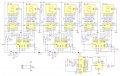
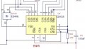
Attached is the schematic of part of a circuit which shows a ripple counter with a reset circuit. The counter should count up to 59 and then reset. However it only counts to 39 before resetting. If I attach a X10 scope probe to pin 10 of the AND gate it works correctly.
What is going on here, please?
What is going on here, please?
Attachments
-
 26 KB Views: 37