RF amplifier inverts my signal, how to fix

Thread Starter

ltorres

Joined Oct 17, 2024
25
Hello,

We use rf amplifiers to amplify a pulse signal that will drive a laser diode on and off. The amplifiers we use are becoming obsolete and I had to source a new one.

The original amplifier we were using is NXP BGY588C and it seemed replacing it was a pretty simple task so I chose the NXP BGE788. Looking through the data sheets it seemed it was a drop in replacement but when I was testing it, the new amplifier inverts positive pulse signal into a negative one.

First of all, can some one explain to me why it does that? The only explanation I can come up with is that the BGE788 has a phase response range. I would have thought that the phase only gave it a time delay, which, on a sine wave and a square wave I can measure a slight delay response (a few nanoseconds.)

I am already looking for other replacements but I want to be sure I understand why that happened, and avoid my purchasing mistake.

Also, what would be the best way to invert the signal in order to salvage these 2 amplifiers I bought. I have a pulse inverter A-PPI-D which kind of works but I still get a really high negative voltage signal which I would like to try and avoid.

Thank you.
 

Attachments

Papabravo

Joined Feb 24, 2006
22,095
RF amplifiers normally work with AC signals and for those the inversion does not matter. Your use of an RF amplifier for a unipolar pulse may work fine for a device that does not invert, but as you have discovered it works "less fine" for one that does. Short of inverting the input pulse I'm not sure what you should do.

ETA:
What exactly are the details of the input pulse?​
 

Thread Starter

ltorres

Joined Oct 17, 2024
25
RF amplifiers normally work with AC signals and for those the inversion does not matter. Your use of an RF amplifier for a unipolar pulse may work fine for a device that does not invert, but as you have discovered it works "less fine" for one that does. Short of inverting the input pulse I'm not sure what you should do.
Yeah that's usually how I test them. I input a sine wave and look for the gain to be relatively fine and send em off.

ETA:
What exactly are the details of the input pulse?​
I am not entirely sure tbh. All I know is that its a range of discrete signals and I can test the 20MHz or 80MHz pulse signal of a few millivolts. Although the signal is inverted the gain is fine.
 

Thread Starter

ltorres

Joined Oct 17, 2024
25
Do you think if two of those amps were connected in series it might convert back to a positive pulse?
Hehe, yeah this was going to be my next experiment. I was just afraid of amplifying the signal too much. I'll have to find some attenuators first.
 

0ri0n

Joined Jan 7, 2025
179
The original amplifier we were using is NXP BGY588C and it seemed replacing it was a pretty simple task so I chose the NXP BGE788. Looking through the data sheets it seemed it was a drop in replacement but when I was testing it, the new amplifier inverts positive pulse signal into a negative one.
First of all, can some one explain to me why it does that?
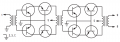
Look at the simplified circuit of such a high gain CATV amplifier/power doubler shown below. Depending on what pin (8 or 9) you choose as output, the input signal will be inverted or not. Using pin 8 of the BGE788 hybrid amp as output and pin 9 as common (GND) should make it non-inverting. Check with an Ohmmeter first if both these pins are floating with respect to common (GND) and if there is a short circuit between them. Note that there are CATV hybrid amps that use a current instead of a voltage balun at in-/output and those will show no DC short circuit between pin 8 and 9.

CATV_Hybrid_Amp.png
 
Last edited:

MisterBill2

Joined Jan 23, 2018
27,869
The solution would be to use a different IC device, or are you using the inline amplifier? ANALOG DEVICES company also makes amplifiers and probably they make one that would work very well.
 

Thread Starter

ltorres

Joined Oct 17, 2024
25
Do you think if two of those amps were connected in series it might convert back to a positive pulse?
I tried this and they actually do make the signal positive.

Look at the simplified circuit of such a high gain CATV amplifier/power doubler shown below. Depending on what pin (8 or 9) you choose as output, the input signal will be inverted or not. Using pin 8 of the BGE788 hybrid amp as output and pin 9 as common (GND) should make it non-inverting. Check with an Ohmmeter first if both these pins are floating with respect to common (GND) and if there is a short circuit between them. Note that there are CATV hybrid amps that use a current instead of a voltage balun at in-/output and those will show no DC short circuit between pin 8 and 9.

View attachment 341145
I am still stuck on this one, I am trying to come up with a jig that doesn't add so much noise. I am still hopeful this works

The solution would be to use a different IC device, or are you using the inline amplifier? ANALOG DEVICES company also makes amplifiers and probably they make one that would work very well.
Yeah, its used as an inline amplifier and I will have a look at analogue devices, thanks.
 

MisterBill2

Joined Jan 23, 2018
27,869
Adding another amplifier prior to the final amplifier, but not an identical amp, unity gain would be OK as well.
The difference in this application is that the amp is just used because of it's adequate high speed response. It might even be worth the effort of contacting the amplifier manufacturer and explain the requirements. There may already exist a suitable product.
 

Thread Starter

ltorres

Joined Oct 17, 2024
25
Look at the simplified circuit of such a high gain CATV amplifier/power doubler shown below. Depending on what pin (8 or 9) you choose as output, the input signal will be inverted or not. Using pin 8 of the BGE788 hybrid amp as output and pin 9 as common (GND) should make it non-inverting. Check with an Ohmmeter first if both these pins are floating with respect to common (GND) and if there is a short circuit between them. Note that there are CATV hybrid amps that use a current instead of a voltage balun at in-/output and those will show no DC short circuit between pin 8 and 9.

View attachment 341145
I was hoping this would work but after coming back to work on this project, I get too much unwanted noise and while the signal doesn't invert it I am simply not getting the gain from the amplifier.

I am looking to use a passive pulse inverter, A-PPI-D from B&H and while this is a decent solution, pricey but workable. The problem is that it introduces a negative pulse signal. This negative signal won't harm much of anything but I would rather it not be there. Would a simple Schottky diode prevent this negative pulse from being there?
 
Top