Facebook
 Google
 GitHub
 Linkedin
MisterBill2
- Joined Jan 23, 2018
- 27,881
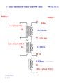
f the 175 turns is placed in series with the 220 volt winding and correctly phased then the voltage will be close to 400volts. It will not be isolated from the mains but that may not be a problem.Hi
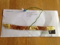
OK have finished winding the pimary back on, have replaced all the plates to check it out and it is giving 6.7v and 13v on the second bobin secondaries, so that all works ok, I am still left with my original question, is how can the transformer output 420v on the secondary that is laid on top of the primary ?.
I just don't understand how 175 turns on a secondary can produce 420v , the leads joining the board say 400v on the board .
Spike