I went back and looked at the PDF of the manual, which states that the high voltage used in the one test is 500 volts DC! So it is very likely that the winding feeds a voltage multiplier circuit and the actual AC voltage may be a lot less than 420 volts, perhaps 210 volts or even less than that. This would explain the lower number of turns in the winding, reported a few posts back. At no-load, a voltage double produces twice the peak to peak supply voltage. So if the output was 500, then the PP would be 250 v, and the RMS about 0.707 of that, I think. That would be close to what is predicted by the turns count reported.
I went back and looked at the PDF of the manual, which states that the high voltage used in the one test is 500 volts DC! So it is very likely that the winding feeds a voltage multiplier circuit and the actual AC voltage may be a lot less than 420 volts, perhaps 210 volts or even less than that. This would explain the lower number of turns in the winding, reported a few posts back. At no-load, a voltage double produces twice the peak to peak supply voltage. So if the output was 500, then the PP would be 250 v, and the RMS about 0.707 of that, I think. That would be close to what is predicted by the turns count reported.
Hi
Thank so for your reply, yes that could be the answer and would solve my query. But why would the makers of the transformer say that winding has a output of 420v @ 3mA .
I see an interesting problem with those numbers. This transformer is, I think, physically rather small. When I consider the voltages and currents listed: 420 V x 3A =1260 watts, +6V x 32A =192 watts +13V x 0.40A = 5.2 watts, a total of about 1450 watts, that transformer is not close to large enough to supply that much power. So I am guessing that secondary #1 is really 420 volts at 0.03A =12.60 watts. And looking at the wire sizes that is more reasonable.
If you have already removed one winding and counted the turns, you can establish the Turns/volt from this and all the other winding's should fall in to this turns/volt ratio.
I went back and looked at the PDF of the manual, which states that the high voltage used in the one test is 500 volts DC! So it is very likely that the winding feeds a voltage multiplier circuit and the actual AC voltage may be a lot less than 420 volts, perhaps 210 volts or even less than that. This would explain the lower number of turns in the winding, reported a few posts back. At no-load, a voltage double produces twice the peak to peak supply voltage. So if the output was 500, then the PP would be 250 v, and the RMS about 0.707 of that, I think. That would be close to what is predicted by the turns count reported.
Going to the trouble already of re-winding.
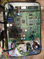
I would be inclined to to a little remedying, the board already looks like it is started to char, and only get worse.
If there is room, the resistors could do with stand offs or stand off style.
Going to the trouble already of re-winding.
I would be inclined to to a little remedying, the board already looks like it is started to char, and only get worse.
If there is room, the resistors could do with stand offs or stand off style.
It is a VERY poor design to have high wattage resistors mounted against a circuit board, as the photo shows. In addition I see what looks like a cracked small resistor just below the relay next to those high wattage resistors.
The high wattage resistors should be spaced at least 1 cm, or half an inch, off the circuit board to allow adequate cooling air and avoid charring the board material.
AND I see the green and grey wires at the terminals marked "400 volts", but O do not see evidence of any voltage multiplier circuit. Of course there is a fair amount that does not show at all, or possibly the doubler circuit is on the opposite side of the board.
Hi
Thanks for your reply, as I said earlier bad design, will sort things out when I can get the secondary winding sorted, I am in a bit of a quandrum, I can get hold of smallish step up transformer 230v to 410v , but I have to be sure that the secondary windings output is 420v, I am going to put the laminates back in and test the out put of the other 2 primary's, just to make sure they are 6v and 12v, then if they check out !.
Spike
edit: 4.10.21 pic of the top side ( marked with transformer input and outputs ) and underside of the board !. for a Robin SmartPAT 3000 .
If I bolt the laminates as per picture will that cause any probs, also I can't get all the laminates back in 3 missing, this is now just to test the output of the 2 secondarys and fire up the tester itselfto see if the board is ok, before I sort the 420v winding out
ps: Just a quickey guy's , first thing, I am not trying to fix this to use has a PAT tester , it is purely a challenge for me .
I was about to mention, most through-bolts have at least and insulator on one end or the other, both ends not really needed.
You need to insulate the bolt stem as well as the head for a short distance in.
Keeps the bolt off the lamination's.
I was about to mention, most through-bolts have at least and insulator on one end or the other, both ends not really needed.
You need to insulate the bolt stem as well as the head for a short distance in.
Keeps the bolt off the lamination's.
While I saw someone had answered this similarly, here is some extra information/explanation.
I have also added a description of why they use or don't use multicore wires in a setup like this in the bottom of this post. Yes, you can use a single-core wire in the secondary,in your case the multicore wire acts as a single core wire, things like that where in the past sometimes done in transformer for devices like fridges. Why: your circuit runs from mains power so it is low frequent(50 or 60 hz), low voltage(230 or 120 volt), so the multistrand wire will work as one wire just like a single core wire of a similar diameter. since the wires inside of the multicore are either in parallel and in this case physically touching and conducting with each other the number of windings in your formula is just the same as the physical amount of windings, this is not the case for a bifilar coil since there the cores are electrically isolated and connected in series(this is just so you can view a physical example of when you will need to use a higher amount of windings in the calculation) However: in the following cases, you should treat it differently/ possibly avoid multicore wires, or specifically use them.
The voltage is very high, this can cause differences in behaviour, and it will quite likely. this depends on many factors as well, however, a general problem you can expect is the resistance since high voltage tends to go more towards surface conductivity rather than volume conductivity. for this, a loosely made multicore wire might be desired as an output wire in a very high voltage setup.
The frequency is very high, sometimes high-frequency setups with multicore wires can react different from single-core wires, these effects are in most cases not that extreme, however, performing tests might tell the answer. this has too many factors in it to properly use in a formula, and many of such factors can not be realistically determined in a realistic scenario. it is also very unlikely to cause a problem in most cases but if you get weird problems in a high frequent setup it might be worth looking at it. the simplest way if you encounter something that might be a problem or inefficiency because of this would be to experiment/test it with 2 setups.
The individual cores are electrically isolated from each other and connected in a non-parallel manner, or any of the other described effects is of play. when you isolate the strands from each other they can act more like individual wires, and so if you connect the strands in strange ways this can give different effects, this, however, is something you will need to do on purpose and you can likely clearly see it in most cases.
Multicore vs Single-core, Why?: in most cases they perform the same, so why do people choose to use one over the other? in the past and even currently in smaller manufacturers they just do it random, or actually with what they have around, or produce themselves.
in more properly designed cases: multicore wire is more expensive, more bulky and harder to make, it is however used in cases where the device might get a lot of vibration on it, or when it needs to be flexible. multistrand is avoided often due to the cost associated, and the increased size due to it's bigger sized isolation. single-strand wire, however, will break very rapidly when you bend it a few times, especially when it is warm due to the current going through it, in which case even vibration might eventually damage the cable. single core cable however can perform better on high amperage at very low voltage, and it will keep its shape to how you bend it. it also makes it a lot easier to make square corners since multi-core wires tend to not bend as sharp and to automatically go to a more round shape.
So in most general transformers a single core wire is more eazy to use, and more economical, as well as more efficient due to the coil being able to be made more compact. on very low voltage high amperage it brings especially more positive effects.
Hi
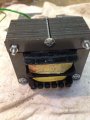
OK have finished winding the pimary back on, have replaced all the plates to check it out and it is giving 6.7v and 13v on the second bobin secondaries, so that all works ok, I am still left with my original question, is how can the transformer output 420v on the secondary that is laid on top of the primary ?.
I just don't understand how 175 turns on a secondry can produce 420v , the leads joining the board say 400v on the board .
 Facebook
 Google
 GitHub
 Linkedin


")


