Rewiring a Transformer

Thread Starter

spike1947

Joined Feb 4, 2016
496
Hi
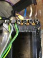
I have a Transformer , I need to rewire one of the Secondary windings, the wire on it is a muti-core wire 9 strands soldered together (0.06mm x 9) not seen that before always been single stranded, question, is that multi core counted has one turn, and could I use a single core equating to the same mm2.
Edited 22:22
cheers
Spike
 
Last edited:

Thread Starter

spike1947

Joined Feb 4, 2016
496
What is the function of the transformer, very unusual to have multi stranded pri.
Have done a bit of a drawing, I have said a second primary, but could be wrong there, it is wired over the top of the main primary 120/240v input, I think it is a 400v output :, there is 2 secondary windings, 1x 13v and 1x 6v, the Grey and Green cables on the left is the winding I am re-wiring, the Blue / White / Bown on the right are the mains feed to the Primary windings 120/240v
 

Attachments

MaxHeadRoom

Joined Jul 18, 2013
28,619
The primary winding is usually wound first, so to modify, the secondary winding's would need to be removed.
But I assume you are retaining the 120v/240v primary and modifying the secondaries?
 

Thread Starter

spike1947

Joined Feb 4, 2016
496
The primary winding is usually wound first, so to modify, the secondary winding's would need to be removed.
But I assume you are retaining the 120v/240v primary and modifying the secondaries?
Hi
Thanks for your reply, I am going to remove the Primary P1 Winding ( that is were the fault is ) , but have had to remove that winding that was laid over that, so that is a secondary winding !, even though it is on the Primary side ?,.

So the enquiry is about the secondary winding that is laid over the Primary winding .
Cheers
Spike
 

William Ketel

Joined Jan 23, 2018
16
I suggest examining very carefully the portion of the winding that connects towards the brown wire. Between the end terminal and the next terminal part of it does not look quite right. Often, winding breaks are near terminals which have been moved a bit.
ALSO: a transformer only has one primary, which may be tapped, or even split. There is no limit to the number of secondaries. The primary is the power input winding, no matter where the terminals are located.
 

MisterBill2

Joined Jan 23, 2018
18,176
YES, that is another possibility, although if it is a dual voltage transformer and the blue is neutral, having it on the high voltage side would be unusual.
AND HEY! I got my handle back.
 

Thread Starter

spike1947

Joined Feb 4, 2016
496
I suggest examining very carefully the portion of the winding that connects towards the brown wire. Between the end terminal and the next terminal part of it does not look quite right. Often, winding breaks are near terminals which have been moved a bit.
ALSO: a transformer only has one primary, which may be tapped, or even split. There is no limit to the number of secondaries. The primary is the power input winding, no matter where the terminals are located.
Hi
Thanks for your reply, yeh the connections to the Primary winding were wound round each terminal and then soldered, I have de-soldered the Blue Neutral and the Brown Live connection, so will look a bit messy just left them there for now , before I start to re-wind the Primary winding .
 

MisterBill2

Joined Jan 23, 2018
18,176
If the conductors are soldered together, or even just not insulated, that is just a single conductor and there is no benefit aside from being more flexible. And there was no mention about the multi-strand being insulated, but usually stranded wire has much thicker insulation than what is used to wind transformers with.
What was, or is, the purpose of the added winding? In a transformer that size it does not seem reasonable that a wire that large would have enough turns to provide 400 volts. And looking at the setup, it appears that the transformer is a split-bobbin style, with primary and secondary on opposite sides of a barrier.
So once again, what is the application for this transformer, and what was powered with that additional winding?
 

Thread Starter

spike1947

Joined Feb 4, 2016
496
If the conductors are soldered together, or even just not insulated, that is just a single conductor and there is no benefit aside from being more flexible. And there was no mention about the multi-strand being insulated, but usually stranded wire has much thicker insulation than what is used to wind transformers with.
What was, or is, the purpose of the added winding? In a transformer that size it does not seem reasonable that a wire that large would have enough turns to provide 400 volts. And looking at the setup, it appears that the transformer is a split-bobbin style, with primary and secondary on opposite sides of a barrier.
So once again, what is the application for this transformer, and what was powered with that additional winding?
Hi
Thanks for your reply, it powers a Portable Appliance Tester.

ps: Yes each strand is lacquer coated !.

cheers
Spike
 

Attachments

Thread Starter

spike1947

Joined Feb 4, 2016
496
Transformer outputs:

1st Sec 1.0 - 420v @ 3mA
2nd Sec 2.0- 6v @32A
3rd Sec 3.0- 13v @ 400mA
 
Last edited:
Top