 Facebook
 Google
 GitHub
 Linkedin
Hi All
I have a project involving the Dynojet Research Dynomometer with Frenelsa 192 volt DC retarder.
All was purchased from the US (120V 60H) and brought to Oz (240V 50H).
Retarder can suck up to 30 amp single phase on 120V - Simple answer is to use a really BIG transformer but wanted to keep it neater if I can.
The Theta controller from Dynojet came in either 120V or 240V and I have the 120V of course.
(Strange thing is both the US and "other countries" spec states 240 volt 30 amps supply required - only difference is the Hz??)
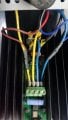
All internals seem to be fine when running on the VariAC at 120V and when wound up to 240V all is still OK save for the fat 12K resistor over the 240 supply (the big blue one in the pic which feeds the 2 x opto couple units to the input signal). I turned it off at 120 C and the beginnings of smoke from that resistor.
This is simply a power supply circuit with 2 SCRs chopping the AC and a Bridge rectifier supplying varying DC out to the retarder on a huge heat sink.
The actual signal comes from the PC software to the small PCB on the other side of controller and all is fine with that - it is just the high voltage side in the picture that is bugging me.
Pic shows the PCB just after I fried the MOV. Cleaned that all up and replaced MOV with a new 260V unit and it runs all OK - in that department.
Everything seems to be rated to 6000 volts???
Anything I have missed please ask - is the resistor maybe not suited to 240V???? (Don't know the current / watt spec on it).
Nothing available from Dynojet - they just want to sell me a complete new setup for $7K ++
I have a project involving the Dynojet Research Dynomometer with Frenelsa 192 volt DC retarder.
All was purchased from the US (120V 60H) and brought to Oz (240V 50H).
Retarder can suck up to 30 amp single phase on 120V - Simple answer is to use a really BIG transformer but wanted to keep it neater if I can.
The Theta controller from Dynojet came in either 120V or 240V and I have the 120V of course.
(Strange thing is both the US and "other countries" spec states 240 volt 30 amps supply required - only difference is the Hz??)
All internals seem to be fine when running on the VariAC at 120V and when wound up to 240V all is still OK save for the fat 12K resistor over the 240 supply (the big blue one in the pic which feeds the 2 x opto couple units to the input signal). I turned it off at 120 C and the beginnings of smoke from that resistor.
This is simply a power supply circuit with 2 SCRs chopping the AC and a Bridge rectifier supplying varying DC out to the retarder on a huge heat sink.
The actual signal comes from the PC software to the small PCB on the other side of controller and all is fine with that - it is just the high voltage side in the picture that is bugging me.
Pic shows the PCB just after I fried the MOV. Cleaned that all up and replaced MOV with a new 260V unit and it runs all OK - in that department.
Everything seems to be rated to 6000 volts???
Anything I have missed please ask - is the resistor maybe not suited to 240V???? (Don't know the current / watt spec on it).
Nothing available from Dynojet - they just want to sell me a complete new setup for $7K ++
Attachments
-
 77.1 KB Views: 8
 -
 129.2 KB Views: 6


