Resucitating a battery charger ?

Thread Starter

Externet

Joined Nov 29, 2005
2,672
Hi.
Its switching power supply has two sections, the mains; and the isolated DC.
The transformer has two secondary windings; one feeds a 7805 to supply the sensing/management electronics and the other to provide the charging current.

The mains side has four unreadable smoked resistors around the mosfet, perhaps this too.

The plan is to delete the mains section and install a linear transformer instead, to come up with 5V and ~15V? to make the isolated section work. It recharges a 3 cell Li-ion pack for a drill.
The capacitors are rated 35V
There is two optocouplers to control the mains section.
---> http://www.toolsandmachinery.com/images/diagrams/UC10SFL.jpg

What are the chances for success, and what should be taken in account ?

Or, does anyone have this Hitachi UC 10SFL that can tell me the values of components ?
 

Thread Starter

Externet

Joined Nov 29, 2005
2,672
Plenty of time; lots of component bins, and I would by it when I find a job. But the question was technical...
 

wayneh

Joined Sep 9, 2010
18,151
I think a picture would help. Impossible to speculate without more detail.

IMHO, if the existing transformer is OK and not shorted or open, it might be worth repairing the other electronics. They are relatively inexpensive whereas the transformer is most of the cost of the charger.
 

Thread Starter

Externet

Joined Nov 29, 2005
2,672
Thanks. The switching transformer is healthy, but exploded resistors are unrecognizable to replace. It looks just as any switcher. And schematics?... yes, a dream.
 

Thread Starter

Externet

Joined Nov 29, 2005
2,672
OK, you win...

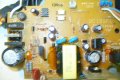
Left section is the kaput mains.

-ZD1 zener: no markings, shorted and melty
-R5 blown, readable, 4.7 ohm
-R8 blown, unreadable
-R9 blown, seems was 0.33 ohm
-FET1, K2617, probably bad, as R5 and the vaporized, go to its gate.

underneath:
-vaporized surface mount resistor or capacitor, just pads left
-Blown SOT transistor, unreadable
 

Attachments

wayneh

Joined Sep 9, 2010
18,151
Now I understand your first post - you want to make a franken-charger instead of fixing the lefthand side of this one. Wall-wart transformer + smart charger circuit = fixed charger.

The component density is not too awful - maybe you could trace the schematic yourself. Or at least enough to do the hack you want. You mentioned a component on the back, though. It gets very hard if there is more than one layer.
 

Thread Starter

Externet

Joined Nov 29, 2005
2,672
Yep.
Removal of the left mains components, leave the cord and perhaps F1, C1, L1 = fuse and line filter, put a linear wallwart transformer on it instead. I could add a power switch if want to be picky.

Now what about the optoisolators... That is what concerns me. Ignore and try/evaluate/measure ? -They are supposed to tell the swicher to somewhat regulate voltage and shut down if no battery is inserted or in any trouble... I think.
The components at the underside left mains section become irrelevant, to delete too.

It is more complicated than this one:
http://www.analog.com/library/analogDialogue/archives/31-2/Graphics/figure3LG.gif

Know of nobody daring to do something like this, yet.
 
Last edited:

THE_RB

Joined Feb 11, 2008
5,438
That 8pin ST brand chip at the top is the SMPS controller. You can download the datasheet for that, which should have schematics or separately downloadable schematics/user guides etc.

R7 and R9 are likely ok.

The gate resistor is R8? That's not good, there has been severe current through R8 and the other end of R8 likely goes to a pin on the SMPS controller IC.
 

Thread Starter

Externet

Joined Nov 29, 2005
2,672
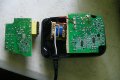
Well... done.
Seems to work, all energized, no smoke, when battery is inserted led charging indicator lights up, after 5 seconds turns off as I already charged the cells individually outside, perhaps is sensing they are fully charged. Future will tell any tweaks needed.
A piece of sponge tucked in to avoid rattling, and to another thingy.
 

Attachments

wayneh

Joined Sep 9, 2010
18,151
Amazing job! Well done.
In my experience, though, a transformer of that (small) size will overheat with the current needed for a battery of that size. You may want to keep a close eye on that.
 

Thread Starter

Externet

Joined Nov 29, 2005
2,672
Correct, and aware of.
That is a transformer with the proper voltage I had in my bins and fits in the housing.

Being lower power capable; if the charging circuit is as 'intelligent' as should, well, if takes longer time to charge by limiting the current to keep the voltage leveled, am happy with it.

Tried to canibalize/transplant the whole mains section from another switcher but my stock of 'junk' is not varied enough for a good match.

Will see...
 
Top