Resistance Value in LED Circuit

Thread Starter

Meech

Joined Jul 22, 2017
12
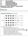
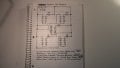
I've fried 2 panels of 20 LEDs each. I believe the resistance values are incorrect. I did the manual calculations and used an LED calculator/wizard from led.linear1.org/led.wiz. (Result pictured below). I'm trying to build some LED panels with 20 LEDs grouped in 4s for total of 5. I've sketched out my schematic based on the layout from the wizard in the configuration I needed (pictured below). The values used are also pictured below, 12 volt source, 3 volt drop (forward), current 20ma X 20 LEDs. The wizard suggested a series/parallel configuration and that is what I based my schematic off of, but when I apply voltage to the built circuit, the LEDs light for a millisecond and then nothing. The first board I thought maybe I made a careless wiring mistake, the second I knew everything was wired properly but it failed as well. So in obvious fashion, I'm missing something and would appreciate a double check.
 

Attachments

#12

Joined Nov 30, 2010
18,224
You have allowed zero volts in excess of the LED requirements. That ended up with zero for the calculated resistance. Cut this down to (3) LEDs per series string and waste 3 volts in the 150 ohm resistor. Better yet, measure the voltage required by the LEDs and discover that they always have a range of voltages over which they operate correctly. Then consider the fact that there is no law which says you must operate LEDs at the highest current they are rated to survive.
 

wayneh

Joined Sep 9, 2010
18,104
A few thoughts. Is your 12V source really a regulated 12V? You’re running the LEDs near their rated maximum and you have no wiggle room. I’d have aimed for 5mA and then see if you want it brighter. This would have allowed you to measure the actual voltage across the LEDs, which I suspect was not really 3V.

Your arrangement works on paper but the devil is in the details.
 

WBahn

Joined Mar 31, 2012
32,847
Let's see the impact that some actual numbers might make. Let's say that all of your stated values are within 5%.

Instead of 3.0 V, your LEDs actually have a forward drop of 2.9 V. (which is only 3.3% less)

Instead of 12.0 V, your power source actually has a voltage of 12.5 V (which is only 4.2% more)

Instead of 1.0 Ω, your resistors are only 0.95 Ω (which is only 5% less).

So now your LED current would be (12.5 V - 4·2.9 V) / 0.95 Ω = 947 mA, or nearly 50 times what you were shooting for.

Depending on what you are using as your 12 V source, you might easily be getting significantly more than 12 V -- for instance a 12 V lead acid battery is typically charged to somewhere between 13 V and 14 V.

You want the voltage across the current limiting resistor to be at least comparable to the uncertainty in the residual voltage dropped after the diodes -- and even that will leave you with an uncertainly in the current of up to 100%, so you would want to target an LED current of no more than half the maximum rating.

As an alternative, let's go with 3 LEDs across 12 V and target 10 mA.

Your series resistor would be 300 Ω.

Now let's see what happens with an uncertainty in all of the figures of 20% in the direction of more current.

Battery: 14.4 V
LED: 2.4 V
Resistor: 240 Ω

Current: (14.4 V - 3·2.4V) / 240 Ω = 30 mA

These are pretty extreme variations, yet they would likely let your LEDs survive for quite a while.

If you do the same thing with a 10% deviation, then the current works out to 19 mA.
 

ebeowulf17

Joined Aug 12, 2014
3,307
EDIT: WBahn beat me to it!

No spec is ever perfect. Imagine what happens if the LED forward voltage is off at all from your expectations.

If, instead of Vf of 3, it was 2.9V each, you'd have 11.6V per string across the LEDs, leaving 0.4V to drop across the resistor. With a 1 ohm resistor, that would be 400mA through each leg. At twenty times the rated current, the LEDs wouldn't last long!
 

MrChips

Joined Oct 2, 2009
34,817
LEDs need a constant current source.

How does one create a constant current source?
An ideal constant current source would have infinite internal resistance.
A non-ideal constant current source should have as high internal resistance as possible. The higher you make the resistance, the closer it gets to becoming an ideal constant current source.

A 1Ω resistor is on the far extreme away from anything that would resemble a constant current source.
 

Thread Starter

Meech

Joined Jul 22, 2017
12
A few thoughts. Is your 12V source really a regulated 12V? You’re running the LEDs near their rated maximum and you have no wiggle room. I’d have aimed for 5mA and then see if you want it brighter. This would have allowed you to measure the actual voltage across the LEDs, which I suspect was not really 3V.

Your arrangement works on paper but the devil is in the details.
wayneh, thank you for the reply, it is appreciated. I was using my bench power supply for the testing, Final power source would have been a regulated 12V. I'm not trusting my math at this point. I tried plugging 5mA instead of the 20mA in the the "wizard", I expected the resistance value to go up, it didn't. Changing the forward voltage does affect resistance values slightly. Do I need to limit the current to the circuit? If i understand, you are saying that the LED forward voltage drop may not be what they are rated at? I have always used the manufacturers specs for calculations. You're right about the devil being in the details, just when you think you have your head wrapped around something, you find out how wrong you are.
 

Thread Starter

Meech

Joined Jul 22, 2017
12
Let's see the impact that some actual numbers might make. Let's say that all of your stated values are within 5%.

Instead of 3.0 V, your LEDs actually have a forward drop of 2.9 V. (which is only 3.3% less)

Instead of 12.0 V, your power source actually has a voltage of 12.5 V (which is only 4.2% more)

Instead of 1.0 Ω, your resistors are only 0.95 Ω (which is only 5% less).

So now your LED current would be (12.5 V - 4·2.9 V) / 0.95 Ω = 947 mA, or nearly 50 times what you were shooting for.

Depending on what you are using as your 12 V source, you might easily be getting significantly more than 12 V -- for instance a 12 V lead acid battery is typically charged to somewhere between 13 V and 14 V.

You want the voltage across the current limiting resistor to be at least comparable to the uncertainty in the residual voltage dropped after the diodes -- and even that will leave you with an uncertainly in the current of up to 100%, so you would want to target an LED current of no more than half the maximum rating.

As an alternative, let's go with 3 LEDs across 12 V and target 10 mA.

Your series resistor would be 300 Ω.

Now let's see what happens with an uncertainty in all of the figures of 20% in the direction of more current.

Battery: 14.4 V
LED: 2.4 V
Resistor: 240 Ω

Current: (14.4 V - 3·2.4V) / 240 Ω = 30 mA

These are pretty extreme variations, yet they would likely let your LEDs survive for quite a while.

If you do the same thing with a 10% deviation, then the current works out to 19 mA.
Thank you, please ignore any other replies I've made in this thread as I didn't see these posts prior to responding. this pretty much explains what I was missing and I appreciate your time explaining, really, thank you!
 
Nice thread everybody. The Wizzard either needs some fuzzy logic or you need a new Wizzard.

Comments:
1. No wiggle room
2. The forward voltage has a range
3. If you bin by forward voltage, those in the same bin would have less intensity variation between themselves.
 

WBahn

Joined Mar 31, 2012
32,847
Thank you, please ignore any other replies I've made in this thread as I didn't see these posts prior to responding. this pretty much explains what I was missing and I appreciate your time explaining, really, thank you!
Try not to rely on "wizards" to do your thinking for you. Learn how to do the design yourself as much as possible, particularly the basic stuff.

The forward voltage across an LED is an average voltage at a particular current at a particular temperature. Different LEDs from the same wafer operated under the same conditions will have slightly different forward voltages. As the LED warms up the voltage across it will decrease -- which is why it is seldom a good idea to put LEDs directly in parallel because one will heat up a bit more than the others and it will then hog more of the current, which will cause it to heat up further and hog even more of the current. A process known as thermal runaway and seldom ends well.

One of the big things you need to learn how to do is to allow for tolerances. For instance, I just looked up a data sheet for a pretty generic green LED and at 20 mA the forward voltage is spec'ed to be between a minimum of 1.8V and a maximum of 2.2 V, so 2 V ± 10%. You need to allow for the possibility that all of your LEDs are at one end or the other of that span.
 

Thread Starter

Meech

Joined Jul 22, 2017
12
Gentlemen, again, thank you! You have taught me a great deal this evening. Hard pill to swallow to realize you have been doing things wrong for a lot of years. I had always assumed spec sheet values for LEDs were typical not their maximum. The LEDs I'm using are the clear lens ultra bright variety rated 3.2 - 3.4 forward V (IF) @ 20ma. Supply voltage with be a regulated 12V. After taking your advice, will go with 3 LEDs per series leg at 10mA and taking 10% for the variances will go with a 330 Ohm resistor per leg.

I'm also a member of K.I.S.S
 

Attachments

Top