Reset a Microcontroller

Thread Starter

engr_david_ee

Joined Mar 10, 2023
358
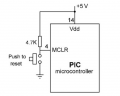
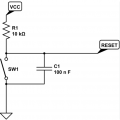
I have found attached reset circuits for a Microcontroller having active low reset pin. Basically they both are doing the same job.

When the button is pressed, the reset pin will be connected to GND which reset the Microcontroller. Otherwise in normal operation the reset pin will be pulled up to 5 V.

We have a situation in which we have two Microcontrollers.

The 1st Microcontroller need to reset the 2nd Microcontroller only when it drive a reset signal to the second Microcontroller. Otherwise the 2nd Microcontroller must be on all the time.

If the 1st Microcontroller is power down for some reason, the 2nd Microcontroller must be on all the time. The 1st Microcontroller can only reset the 2nd Microcontroller when it wants. In default state or even when there is no power at the 1st Microcontroller, the 2nd Microcontroller must be on all the time.

I need a suggestion which circuit should I use.
 

Attachments

nsaspook

Joined Aug 27, 2009
16,259
Make sure the reset GPIO output from the first controller is a open collector or drain type/configuration, default (high) so the power up RC (pull-up resistor and cap) delay can still work correctly on the 2nd controller.
 

nsaspook

Joined Aug 27, 2009
16,259
With PICs, I have never used an RC reset circuit, just a pullup.
You might need extra delay for power supply and module (like internal clocks or crystal osc) stability on power-up. The Power-Up Timer (on most chips) gives some delay but it might not be sufficient for all applications. Belts and Suspenders for the cost of one cheap component. I don't know why the OP is using two controllers but it's a good idea to make sure it's all stable before executing code.

https://ww1.microchip.com/downloads/en/AppNotes/00000607C.pdf
Power-up Trouble Shooting
 

BobTPH

Joined Jun 5, 2013
11,467
I understand all of that, but one of the two pushbutton circuits he posted did not have the RC delay, so I assumed he did not meed it. Easy enough to add if it is needed.
 

nsaspook

Joined Aug 27, 2009
16,259
I understand all of that, but one of the two pushbutton circuits he posted did not have the RC delay, so I assumed he did not meed it. Easy enough to add if it is needed.
He asked which one to use from the two he posted and I always use the one with a delay for reset unless there is a need for very quick reset times with external sequenced power 'good' signals.
 

Thread Starter

engr_david_ee

Joined Mar 10, 2023
358
Using capacitor in the reset circuit there will be some RC delay which is fine.

I think I just need to remove the push button at the second MCU reset circuit connect to the GPIO of the first MCU.

The problem is that if the first MCU is power down then how we can ensure the second MCU still running normal without reset.
 

nsaspook

Joined Aug 27, 2009
16,259
Using capacitor in the reset circuit there will be some RC delay which is fine.

I think I just need to remove the push button at the second MCU reset circuit connect to the GPIO of the first MCU.

The problem is that if the first MCU is power down then how we can ensure the second MCU still running normal without reset.
No need for the second button but I would have a pin header (populated or not) or TP for a manual reset and/or signal tracing.

How do you ensure the controllers are running normally when both are powered up?
 

AlbertHall

Joined Jun 4, 2014
12,620
I think you need something on the reset line to the second uC otherwise the pull-up on the second uC will feed voltage back to the first uC when it is powered down. This could be a bjt or MOSFET in the position of the switch on the second chip which is turned on by a signal from the first.
 

Thread Starter

engr_david_ee

Joined Mar 10, 2023
358
I think I need to add some logic when it comes to reset the second MCU. The second MCU need to be ON all the time, so there has to be a pull-up along with a capacitor that provide some RC delay to MCLR_N pin of the second MCU.

Reset the first MCU is a separate mechanism and is completely out of question because the power source is different for the first MCU. The reset of the second MCU is the point of discussion in this post.

The challenge is when the first MCU is down and not powered up, the second MCU need to be running normal without going to reset. This means that the first MCU can only reset the second MCU as an option but the first MCU is even not needed to enable or keep the second MCU working.

If the first MCU is powered up and working normal only then it can reset the second MCU. Otherwise the second MCU should have MCLR_N pin pull-up to 3.3 V all the time.
 

AlbertHall

Joined Jun 4, 2014
12,620
If the first MCU is powered up and working normal only then it can reset the second MCU. Otherwise the second MCU should have MCLR_N pin pull-up to 3.3 V all the time.
But if the first is powered down and the reset on the second is at 3.3V then if that reset pin is connected to a pin on the first then it will feed that 3.3V, through the pin protection diodes, to the power rail of the first.
 
Top