Request help for an end of task alert buzzer sub-circuit.

Thread Starter

mjncad

Joined Feb 11, 2018
6
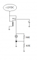
I'm trying to get a 12 VDC sub-circuit to function that will activate a buzzer at the completion of a task and the power has been cut to the main circuit. The buzzer should sound for about 10 - 15 seconds before turning off. I've accomplished this with a capacitor bank; but the buzzer doesn't cut off below a certain voltage (5 - 8 volts) and continues operating with a sick fade out sound. Then I read that transistors could be used as a switch; but I'm getting the same effect, just with extra hardware in the circuit.

My background is primarily mechanical in nature, with my electrical experience being AC residential around my house. The last time I tried learning electronics was 45-years ago, which was a disaster due to a teacher that literally said to me, "These pliers are not meant for holding things."

I've attached the sub-circuit schematic as it currently stands. The amp readings are with a LED instead of the buzzer. I've also attached the data sheets of the components I'm using. I've run out of ideas; yet I'm certain something like has to be fairly common using analog components.

Thanks for the help.

Buzzer_Sub-circuit.png
 

Attachments

Dodgydave

Joined Jun 22, 2012
11,284
If you put a Zener diode in series with the R2 resistor say 3.6V this will shut the transistor off at 4.3V (3.6 + 0.7) so the capacitors will be discharged from 12V to 4.3V,,, , or whatever zener you choose to cut off the buzzer.

You can use a Tl431 zener to turn the buzzer on without a transistor if the current is less than 100mA,,
Below is an example, your buzzer would be the led,,these are precision diodes and are programmable using two resistors R1,R2.

lm431-voltage-monitor-circuit.jpg
 
Last edited:

LesJones

Joined Jan 8, 2017
4,174
I assume that resitor R1 (22K) is to limit the charging current to the capacitors. This will not allow enough current to pass to drive the buzzer. There are two ways round this problem. One Move this resitor to between the 12 volt supply andthe NO contact on the relay. Two Put a diode in parallel with this resistor with the cathode (The end with the band on.) to point C. To give a more positive turn off adding a zener diode of about 6.2 volts would help (But not totaly but not totaly.) cure the problem. I think using another small relay like the one in your link would be the simplest for you. Remove the resistors R2 and R3 and the transistor. Connect the new relay coil between point I and ground. Connect the common contact to point I. Connect the buzzer between the NO contact and ground. To do it electronicly I suggest using a comparator (Such as half of an LM393.)
Edit. I've just noticed DD's solution. That is simpler than using a comparator and better then adding a zener diode to your existing circuit.
Les.
 

Thread Starter

mjncad

Joined Feb 11, 2018
6
DD & LJ:

Thank you both for your interest and prompt response to my questions.

I'll reply to LJ first. Originally I wanted to use the same relay (I understand relays) that I used in the schematic I posted; but if I read the datasheet correctly, the cutoff voltage is 1-volt and change, which would more than likely result in the same problem.

The 22k resistor was based on using the following online calculator http://mustcalculate.com/electronics/rctimeconstant.php and it looks like I misread the results when I first ran the numbers. I think it should be a 2k resistor. I also used this calculator. http://mustcalculate.com/electronics/capacitorchargeanddischarge.php

My reply to DD. Your circuit looks simple to me, and I like that since this all new to me. If I understand the basic concept of a Zener Diode, it is similar to a check valve in my piping world. Obviously I need to educate myself further on Zener Diodes and peruse the Digi-Key website.

To DD and LJ. I better run my numbers again through the calculators. If I don't reply with an update relatively quickly it's because I'm also working on other non electronics projects, which gives me the opportunity to set something aside that is stumping me until the Ah Ha moment occurs.

Matt
 

Thread Starter

mjncad

Joined Feb 11, 2018
6
I agree #12 as my calculations show the need for five capacitors for 10-seconds; but I just plugged three into my breadboard just to get the proof of concept going. Surprisingly I was getting about 10-seconds of useful noise with three capacitors that I attribute to the power supply having some capacitors inside.

Fortunately I've left enough room on the permanent breadboard for up to 7 to 10 capacitors depending on what other components I need to get this sub circuit going.
 

Attachments

Thread Starter

mjncad

Joined Feb 11, 2018
6
OK, I did some research on the LM431 and Zener diodes mentioned above. I didn't know shunts like the LM431 existed. To me a shunt has always been for example a movable metal tab in a single phase motor to convert from 120VAC operation to 240VAC.

If I understand the replies above correctly, the R2 and R3 resistors in my original circuit and the ones posted afterwards are used as voltage dividers. Since shunts and Zener's are cheap, I may order a few and bracket my voltages the way photographers do exposing their images. Attached are my interpretations of shunt and Zener approaches to turning my buzzer off at a specified voltage.

Buzzer_Sub-circuit-02.png
 

Dodgydave

Joined Jun 22, 2012
11,284
The zener on the transistor is drawn the wrong way round, also put a 1K resistor in parallel with the buzzer with the Tl431 .

For 7V shutdown use R2 1.8K , R3 1K, or any combination that is 1.8 times the difference.
 
Last edited:

#12

Joined Nov 30, 2010
18,224
A bit of confusion here. The buzzer is rated down to 4 volts. Why stop at 7V if the buzzer still works to 4V?
Judgement call by the Thread Starter if the buzzer gets too wimpy.
 

Thread Starter

mjncad

Joined Feb 11, 2018
6
The zener on the transistor is drawn the wrong way round, also put a 1K resistor in parallel with the buzzer with the Tl431 .

For 7V shutdown use R2 1.8K , R3 1K, or any combination that is 1.8 times the difference.
Noted regarding the Zener with the transistor circuit.

I made the assumption that the buzzer's internal resistance would preclude the need for another resistor. I assume my revised sketch covers the need for a parallel resistor to the buzzer with the TI431 configuration per your comments.

Buzzer_Sub-circuit-03.png
 
Last edited:

Thread Starter

mjncad

Joined Feb 11, 2018
6
A bit of confusion here. The buzzer is rated down to 4 volts. Why stop at 7V if the buzzer still works to 4V?
Judgement call by the Thread Starter if the buzzer gets too wimpy.
The buzzer gets pretty anemic sounding to me below 6 - 7 volts. Although below the buzzer rating, I can hear it down to about 1.5 - 2 volts; though it's barely audible by then.
 
Top