Repairing a blown capacitor in an ATX power supply

Thread Starter

jwharton

Joined Aug 18, 2016
3
I have a power supply (rated at I believe 600-750 watts sticker is gone so I don't know for sure) in my son's computer that died that looks like it can be repaired if I just replace one bad component.

I opened it up and discovered parts of a ceramic capacitor (or thermistor for current regulation?) that was blown.

Unfortunately, because it is in several pieces, which I could not find all of, I cannot make out the numbers that were on it so I don't know what it was.

It is about 3/8" to 1/2" in diameter and about 1/8" thick. It is dark green in color and its position in the circuit is on the AC input side having to do with whether the unit is plugged into a 110VAC or a 220VAC input source. It's label on the PCB is THR1. The A and B labelled wires coming in are from the switch that goes between the two voltages.

Will someone please indicate to me what a suitable replacement component would be?

Thanks!

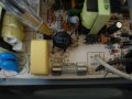
I have some pictures attached if these will help:
20160818_123512.jpg 20160818_123531.jpg
 

Thread Starter

jwharton

Joined Aug 18, 2016
3
No, I have not done any testing of other components.
I'm actually pretty new at attempting such things.
Would you kindly give me some hints on how I can test that bridge rectifier?
I am assuming it is that black box between the two red wires coming in.

Thanks!
 

wayneh

Joined Sep 9, 2010
17,498
The two red wires going to the inner two pins are AC power. The outer two pins are the rectified DC output. You can see the pins are marked + and -.

Do you have a multimeter? If not, get yourself one. The one I use is the one they give away free at Harbor Freight. But even their so-called full price is under $10. You'll never regret getting one.

There are various ways to test the 4 diodes in a bridge rectifier. If you feel safe plugging this thing in, you can check for your AC line voltage on the red wires and a DC voltage between that and 1.4x that level on the "+" and "-" pins. For example 120V AC on the red wires and 160V DC on the outer pins of the bridge.

It's safer to test with the power off. In that case you are looking for continuity in only one direction from each AC ~ to the "+" pin, and in the opposite direction to the "-" pin. By direction, I mean that swapping your meter test leads makes the continuity go away. Each AC terminal should show the same behavior. Your meter will do ohms readings and will also have a diode test setting. Either will be fine for this test.

See that fuse on your PCB? It looks like it's probably OK in the picture but you should check it. If it's blown, don't bother replacing it until you're sure about that bridge.

See that giant capacitor next to the bridge? There's probably ~160V on it if the bridge is working. It's a good candidate to replace, no matter what else is wrong. Electrolytic capacitors age and fail without any change in appearance and a common repair strategy is to simply replace all of them. Worst case, it makes no difference but updates the device to fresh capacitors. Best case, it's all that's needed for the repair.
 

debe

Joined Sep 21, 2010
1,390
Its a surge protector usualy green or black in colour. The resistance goes lower as they heat up. Yours has failed probably due to a short on the bridge rectifier as wayneh has posted.NTC.1.JPG NTC.2.JPG
 

Attachments

Thread Starter

jwharton

Joined Aug 18, 2016
3
I'm wondering if this got blown because about a month ago I introduced 5 1000 watt grid-tie inverters running on 20 solar panels I installed.
I usually have all my computers running behind a UPS line conditioner but this one wasn't.
 
Top