Looks like a, "win". Take the fuse out and replace it with a DC amp meter to find the idle current at this moment. If that's good, put the fuse back in and check DC voltage base q2-1 to base q2-2 looking for 1 to 2 volts DC.
Good means probably less than 0.1 amp. Bad means more than an amp.
So...base Q2-1 to base Q2-2 is about 4 volts?
That would put the idle current of the drivers at .28 amps.
You're only getting 17 ma through R2-13.
Something is wrong with this picture.
R2-17 and 2-18 = 4.7 ohms.
Check the DC voltage across each of them looking for about equal voltages.
That's still about 100 ma idle current. Not bad, but it is arguing with the 17 ma calculation through the 22 ohm R2-13.
Cut power. Ohm r2-13. Restore power. Re-measure voltage across 2-13.
Measure voltage across the 4.7 ohm resistors 2-17 and 2-18
ps, don't forget to wait until DC power voltage goes to zero before ohming resistors.
Both leads on resistor.
If Q2-1 is passing 0.1 amp, it must be getting that from the 22 ohm resistor. That would read 2.2 volts DC across that resistor. If that resistor doesn't have 2.2 volts across it, where is the tenth of an amp coming from???
So...double check by measuring voltage across the pair of 4.7 ohm resistors. That will validate 0.1 amp, or it won't.
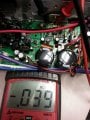
Ok r13 test as 22 ohm . Good . Reading across all three resistor less then 1v . Reading from ground to r13 is 73v . Reading to ground on r17 and r18 is fluctuating 1v - 6v
When I say to measure across a resistor, I don't mean measure compared to ground at, "I don't know how far away that ground point is." I mean, "across the resistor". Shortest path. Test leads ON the resistor if you can do that without drilling through the board to get to the copper side.
Now, try again to measure the voltage across the resistors in question. They have to balance out, current wise, or we're not getting it right.
and yes, they are all supposed to be less than 1 volt DC.
Can you get a steady reading across the resistors? HOW MUCH less than 1 volt is what we're trying to balance the equation with.
V R2-13 /22 ohms = V R2-17 /.47 ohms or it's not right.
The basic design of this driver is that, "ground" is not steady. "Ground" is the driven voltage!
Now you're measuring 1 ma through the 22 ohm resistor R13 and 10 ma through the .47 ohm resistor R17.
and R18 is showing 8 times as much current as R17. AFU!
Go to pin 7 of U2-1B
Measure that to some ground. I don't care if it's wandering. I care whether it is slapped hard against one of it's supply voltages or vaguely centered.
C11 and C12 are ceramic. Very tough capacitors, but they are rated at 50 volts. (I wouldn't build this with less than 100 volt capacitors.) They are in parallel with the alleged 4.7 ohm resistors that are reading, "zero".
I'm afraid you're going to have to unsolder one end (or both ends) of each 4.7 resistor and ohm them while they are thusly not in the circuit.
 Facebook
 Google
 GitHub
 Linkedin