Facebook
 Google
 GitHub
 Linkedin

I needed a bench supply and not being ready to invest in something serious I decided to go cheap.
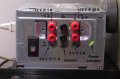
I'm sure you've seen the plethora of ~30V @ ~5A supplies based, at least externally, on the venerable Tektronix PS282 lab supply—this is one of those.
Unlike the original, this one is a switcher. I bought it cheap(!) and so had low expectations which this supply actually managed to fail to meet. It "works", but it has a couple of features that I didn't ask for: periodic impulse noise and terrible low voltage instability.
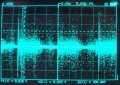
The noise is regular, and consists of ~1.5uS pulses of about 200mV PP, with a following pulse about 1/4 the amplitude 1uS later.
The instability is a positive going, very short voltage about 200mV above the baseline. The supply itself shows this jumpiness on its output display.
I am not familiar enough with switching supplies to know if this is a recognizable fault, or where to start looking for what it wrong. I don't need to repair this thing, and I am replacing it with something much better, but I would like to use it as a bit of a lesson in SMPSs and get the extra bonus of a stable extra supply.
Anyone have any ideas, hints, suggestions, wisecracks, remarks, or sage advice?
I've included a photo of the noise over a few seconds in case that helps.
I'm sure you've seen the plethora of ~30V @ ~5A supplies based, at least externally, on the venerable Tektronix PS282 lab supply—this is one of those.
Unlike the original, this one is a switcher. I bought it cheap(!) and so had low expectations which this supply actually managed to fail to meet. It "works", but it has a couple of features that I didn't ask for: periodic impulse noise and terrible low voltage instability.
The noise is regular, and consists of ~1.5uS pulses of about 200mV PP, with a following pulse about 1/4 the amplitude 1uS later.
The instability is a positive going, very short voltage about 200mV above the baseline. The supply itself shows this jumpiness on its output display.
I am not familiar enough with switching supplies to know if this is a recognizable fault, or where to start looking for what it wrong. I don't need to repair this thing, and I am replacing it with something much better, but I would like to use it as a bit of a lesson in SMPSs and get the extra bonus of a stable extra supply.
Anyone have any ideas, hints, suggestions, wisecracks, remarks, or sage advice?
I've included a photo of the noise over a few seconds in case that helps.
Attachments
-
 295.7 KB Views: 12
Last edited: