Relay Contact Spike Measurement

Thread Starter

ilginsarican

Joined Jul 13, 2017
142
Hello,
I use relay for an AC(115V RMS) load, relay switches on/off both line and neutral.
Schematic is below.
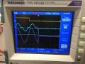
I want to measure spike voltage on relay contact when switch off.(I can see spark on relay contacts)
The load current is 4A RMS, pf:0,85
I did not measure spike voltage pin 8 of relay, I am confused which point should be referance to measurement?
Because the relay both switches line and neutral.
I have tried measurement spike on pin 8 referenced to pin 12, pin 5 ,pin 9 but I could not see any spike.
After relay switches OFF, pin 5 and pin 8 are float points, so I think I could not measure.
I would be glad if you share ideas..


1632237696406.png
 

crutschow

Joined Mar 14, 2008
34,285
Unless you have a isolation transformer for the AC it's dangerous to connect an oscilloscope to measure that spike.
Why do you want to measure it?
You can't do anything useful with that value.
 

Thread Starter

ilginsarican

Joined Jul 13, 2017
142
Unless you have a isolation transformer for the AC it's dangerous to connect an oscilloscope to measure that spike.
Why do you want to measure it?
You can't do anything useful with that value.
Actually I want to calculate RC snubber values.
The channels of oscilloscope are isolated and I am using high voltage probe.
 

strantor

Joined Oct 3, 2010
6,782
You're using the correct measurement points. If you can't see the spike then probably your scope trigger/auto-hold settings are wrong, or your HV probe (active?) Is too slow.
 

michael8

Joined Jan 11, 2015
410
What is the load? Is it inductive? Here's a thought experiment (not realistic, but hopefully informative):

Assume 1 amp is flowing when the relay opens and an inductive load. At the instant the relay opens the
energy coming out of the load due to the current decrease will appear as a voltage high enough for the
1 amp to continue flowing. So the voltage will be whatever it takes for the current to continue to
flow (but rapidly decreasing current).

Your snubber needs to accept this current without the voltage raising high enough to arc over the contacts.
 

Thread Starter

ilginsarican

Joined Jul 13, 2017
142
You're using the correct measurement points. If you can't see the spike then probably your scope trigger/auto-hold settings are wrong, or your HV probe (active?) Is too slow.
Hi,
I have attached an scope screen.
CH2 is current probe, CH3 is voltage of pin-8.
CH1(yellow) is connected to "AC OUT ENABLE" point and is trig signal (falling edge).
The turn off time of the relay is approximately 20ms.
I can see spike on current measurament but not on voltage.
By the way I have connected pin 9 and 5 of relay to use as reference point.
When the relay is turn off, the voltage spike occurs pin 8 right?
Or should I measure between pin 12 and pin 8?
 

Attachments

Last edited:

Thread Starter

ilginsarican

Joined Jul 13, 2017
142
What is the load? Is it inductive? Here's a thought experiment (not realistic, but hopefully informative):

Assume 1 amp is flowing when the relay opens and an inductive load. At the instant the relay opens the
energy coming out of the load due to the current decrease will appear as a voltage high enough for the
1 amp to continue flowing. So the voltage will be whatever it takes for the current to continue to
flow (but rapidly decreasing current).

Your snubber needs to accept this current without the voltage raising high enough to arc over the contacts.
Hi,
Actually I dont know the load exactly, only assumption.(Customer did not give any information.)
 

strantor

Joined Oct 3, 2010
6,782
Hi,
I have attached an scope screen.
CH2 is current probe, CH3 is voltage of pin-8.
CH1(yellow) is connected to "AC OUT ENABLE" point and is trig signal (falling edge).
The turn off time of the relay is approximately 20ms.
I can see spike on current measurament but not on voltage.
By the way I have connected pin 9 and 5 of relay to use as reference point.
When the relay is turn off, the voltage spike occurs pin 8 right?
Or should I measure between pin 12 and pin 8?
You said you were using a HV probe. Is it an active probe (battery inside) or just like 100x passive probe?
 

BobaMosfet

Joined Jul 1, 2009
2,110
It is not unheard of to see spike values 5 times greater than max V. V is a measure of how quickly current is being dumped through an impedance/resistance. Ratiometrically.

I would add a ZC detector and then only switch on or off when at zero, thus eliminating the spike. Could then easily be done with solid-state (SCR), rather than solenoid- solenoid actuated devices take time because they are coil driven.
 

Ian0

Joined Aug 7, 2020
9,675
To calculate the perfect snubber, measure the load inductance and resistance.
Use a resistor that is the same value as the load resistance
Calculate C=L/(R^2)
Connect it across the load.
Whilst it is the perfect snubber, it might not be a practical snubber ,because it might dissipate a lot of power
 

strantor

Joined Oct 3, 2010
6,782
Hi,
I have attached an scope screen.
CH2 is current probe, CH3 is voltage of pin-8.
CH1(yellow) is connected to "AC OUT ENABLE" point and is trig signal (falling edge).
The turn off time of the relay is approximately 20ms.
I can see spike on current measurament but not on voltage.
By the way I have connected pin 9 and 5 of relay to use as reference point.
When the relay is turn off, the voltage spike occurs pin 8 right?
Or should I measure between pin 12 and pin 8?
Hold up... I should have realized this immediately, but: You're measuring across the NO contacts of an energized relay? and getting an AC waveform of >250V? You should be getting close to 0V if the contacts are closed. I think you're measuring across the NC contacts friend; What you're showing on your scope is the closing of a set of contacts, not the opening.
 

Thread Starter

ilginsarican

Joined Jul 13, 2017
142
Hold up... I should have realized this immediately, but: You're measuring across the NO contacts of an energized relay? and getting an AC waveform of >250V? You should be getting close to 0V if the contacts are closed. I think you're measuring across the NC contacts friend; What you're showing on your scope is the closing of a set of contacts, not the opening.
Hi,I am measuring pin 8 while contacts are opening, referenced to pin neutral.
I want to measure if is there any spike on pin 8 while opening.
 

Thread Starter

ilginsarican

Joined Jul 13, 2017
142
Hi,I am measuring pin 8 while contacts are opening, referenced to pin neutral.(scope picture)
I want to measure if is there any spike on pin 8 while contacts are opening.
I have measured 8 referenced to pin 12, I saw 0 volt, which is how it should be.
I have been told that I should measure between contacts(pin 8 and pin 12) to measure spike but I does not make sense to me.
 
Last edited by a moderator:

strantor

Joined Oct 3, 2010
6,782
Hi,I am measuring pin 8 while contacts are opening, referenced to pin neutral.(scope picture)
I want to measure if is there any spike on pin 8 while contacts are opening.
I have measured 8 referenced to pin 12, I saw 0 volt, which is how it should be.
I have been told that I should measure between contacts(pin 8 and pin 12) to measure spike but I does not make sense to me.
Yes, measure across 8 and 12. One does not measure a voltage "on" any point. Voltage is a differential measurement. It only exists across/between two points. Where is this arc occurring? Across the contacts, right? So measure across the contacts as they open, and you'll see your spike.
 
Top