How much current does the electronics draw from the 3.3 volt regulator?
Seems like all you need is a simple resistor in series with the regulator input.
How much current does the electronics draw from the 3.3 volt regulator?
Seems like all you need is a simple resistor in series with the regulator input.
You could use a JFET such as J113. Vgs(th) is higher at 3V, so you would get 6.3V on the regulator input worst case, and 120Ω Rds(on) would still only drop 12mV.
You could use a JFET such as J113. Vgs(th) is higher at 3V, so you would get 6.3V on the regulator input worst case, and 120Ω Rds(on) would still only drop 12mV.
Nothing extra. 120Ω is the resistance it would present if fully enhanced*. You need it to drop 11V. It's going to dissipate 11V*100uA (1.1mW) regardless of its Rds(on) because you are using it in linear mode. Rds(on) is just a sanity-check to make sure it can supply the power. It will have a Rds value of 110kΩ when supplying 100uA from a 16V supply.
*Probably the wrong term when referring to a depletion mode device, but the most "switched-on" that it can get.
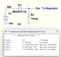
Below is the sim using a 12V Zener to drop the voltage, similar to your post #12.
R2 is to provide a little additional bias current through the Zener so it drops the required voltage.
You may have to reduce its value some if the output voltage is too high in the real circuit.
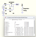
Here's a circuit using a standard N-MOSFET to drop the voltage that draws no bias current.
You need to bring out an additional voltage for the gate, but it draws no current, so has no effect on the battery discharge or charging.
(The Regulator resistor simulates the regulator quiescent current.)
Here's a circuit using a standard N-MOSFET to drop the voltage that draws no bias current.
You need to bring out an additional voltage for the gate, but it draws no current, so has no effect on the battery discharge or charging.
(The Regulator resistor simulates the regulator quiescent current.)
Right ... the thing about the circuit in post #28, is that even though at first one could get exactly 8V out of the battery array, with time said voltage would drop to about 4.5V. Said voltage is still perfectly usable by the regulator and the rest of the circuit. But maybe it'll not be enough to correctly drive the nFet?
with time said voltage would drop to about 4.5V.
......
It clearly show's that the regulator's input voltage is stable at about 7.068V, which is at the regulator's maximum limit.
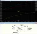
Okay, but your circuit is not a regulator.
It's output is stable for a constant input voltage, but the Zener maintains a constant drain-source voltage, so the gate voltage, and thus the source output will drop with the battery voltage.
To regulate the voltage you need to reverse the resistor and Zener position as in the circuit below, so as to maintain a relatively constant source output voltage:
Okay, but your circuit is not a regulator.
It's output is stable for a constant input voltage, but the Zener maintains a constant drain-source voltage, so the gate voltage, and thus the source output will drop with the battery voltage.
To regulate the voltage you need to reverse the resistor and Zener position as in the circuit below, so as to maintain a relatively constant source output voltage:
Okay, but your circuit is not a regulator.
It's output is stable for a constant input voltage, but the Zener maintains a constant drain-source voltage, so the gate voltage, and thus the source output will drop with the battery voltage.
To regulate the voltage you need to reverse the resistor and Zener position as in the circuit below, so as to maintain a relatively constant source output voltage:
Let’s look at it another way. At 100uA, a 2000mAh battery will last 15000 hours. I wouldn’t worry about that draw unless you expect the batteries to last more that 1500 hours on a charge. What battery life ate you designing for?
Depends upon the reverse leakage current of the Zener, which causes it to go out of regulation.
That varies some from unit to unit, so you would need to test it with the real circuit.
Let’s look at it another way. At 100uA, a 2000mAh battery will last 15000 hours. I wouldn’t worry about that draw unless you expect the batteries to last more that 1500 hours on a charge. What battery life ate you designing for?
The solenoid itself draws about 4A through a 50ms pulse each time it's activated. And the solenoid will be activated about 300 times a day, at the very least.

 Facebook
 Google
 GitHub
 Linkedin