Rectifiying of 125 VAC

Thread Starter

Landon

Joined Oct 3, 2007
9
Hi guys,

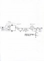
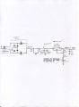
I'm currently building a circuit with an input of 230 VAC, 50Hz. This is being stepped down via a transformer 230/115 VAC, 0.8A, 100VA. But I'm getting around 125 VAC after stepped down, which I think is perfectly alright as a +/- 10% allowance is given to the transformer. After which, this 125 VAC is being rectified through a simple half bridge rectifier which i designed, using 1N4004. What bemused me was that the output I'm obtaining is 170 VDC, which makes no sense. The circuit is attached below.

I've troubleshooted the circuit and have realise that the cause for this (170 VDC) is due to the circuit after the rectifier. I've measured the voltage across rectifier upon disconnecting the 15ohms resistor and it was found out to be around 125 VDC. But when the resistor was connected back, the voltage went up to 170 VDC. (I'm simply perplexed!!)

Can someone explained this phenomenon to me?
 

Attachments

beenthere

Joined Apr 20, 2004
15,819
You are seeing the difference between the RMS valye of the AC waveform, and the peak value of the waveform. AC sine wave power is different from DC in that the value of the voltage continuously changes. RMS measurement is a means to relate the amount of AC power to DC power. You can look into the article in our Ebook for more depth - http://www.allaboutcircuits.com/vol_2/chpt_1/3.html

After rectification, the filter capacitor (capacitors C1 & 2 in your circuit) will charge to peak. The difference between peak and RMS is peak * .707. 170 * .707 = 120.19, somewhat close to the 125 volts AVC measured by your meter. The discrepancy might be that your meter gives the average of the AC waveform, rather than RMS.
 

eblc1388

Joined Nov 28, 2008
1,542
I've measured the voltage across rectifier upon disconnecting the 15ohms resistor and it was found out to be around 125 VDC. But when the resistor was connected back, the voltage went up to 170 VDC. (I'm simply perplexed!!)

Can someone explained this phenomenon to me?
Well the short answer is you are not measuring a pure DC signal but a rapidly changing signal.

Without the 15Ω resistor, there is no smoothing to the rectified AC so the voltage will goes from 0 to 176V and back to 0 at twice the AC frequency. If you connected the 15Ω resistor, then the smoothing capacitor(2x200uF) will help to store up the energy while the AC waveform reaches its peak and that is why the measured DC voltage have gone up to 170V.

Let's look at the circuit via simulation. In the following circuit, the 15Ω resistor is not in the the circuit but switched into the circuit 120mS from start. The resistor R3 is there to represent the input impedance of the DC meter. You will noticed that the DC meter measured waveform changes from wide variations into a smooth(relatively) trace of 170V after the resistor & capacitor are switched in. This also demonstrates the effect of smoothing after rectification.

To obtain both the average and RMS value of the waveform before 120mS, the portion of trace is magnified and it would then work out that the average is about 110V and the RMS is about 124V as shown. If your meter is showing 125V, then it is calibrated to read RMS, as most meters do.

I hope this picture can clear your doubts about the "strange" behavior of the circuit.


Attachments

Thread Starter

Landon

Joined Oct 3, 2007
9
Hi guys,

thank you for your detailed reply. Maybe my explanation is too brief. It's not something related to rms/peak value.

I'll try to make things easier for you guys to understand. Sorry, but my description sucks.

The circuit I'm building is shown as below. My problem is with the output voltage after rectifying which shows 177 VDC. This happens when the two 220uF cap are in place. without the cap, I'm getting the desired voltage, around 115 VDC. I'm thinking whether is it due to my transformer that i'm using, as it is an isolation transformer with technical specifications of

: 230/115 VAC step down transformer
output current = 0.81A
100 VA

Can advise on this?
 

Attachments

alim

Joined Dec 27, 2005
113
Hi Landon may not be being stubborn, he may not be able to see that what is said is indeed part of the answer , some info stated as eblc1388 has done are not readily understood by a beginner ( this not a criticism), but if I can attempt at some clarity, I would say nothing perplexing is happening, what is taking is that after the rectified voltage 125v dc is connected to the capacitors the capacitors charge up to the PEAK VALUE of the AC WAVEFORM that is 125v *1.414=176.75 volts.
 

t06afre

Joined May 11, 2009
5,934
The theory behind this is simple, but not obvious. So Landon just remember that the 220 volt in your mains is the RMS value (root-mean-square value). And most multimeter measure RMS. Simply speaking, the root-mean-square (RMS) value of an alternating voltage is the equivalent d.c. voltage that can deliver the same amount of energy to a resistor as the a.c. does over a cycle.If it is any comfort I once killed a car stereo by by power it from a battery charger with a big 1F smoothing capacitor.
 

t06afre

Joined May 11, 2009
5,934
Yes that is correct. They have also a limited bandwidth. Perhaps around 500-1000Hz. But then measuring on say a mains voltage or mains related voltage, like transformer output. In such cases my statement is valid.
Edit: You will find the AC bandwidth for your multimeter in the data sheet. This number will vary. I have Fluke 189 "true RMS multimeter" This was not a cheap model and the AC bandwidth is 100Khz for current and voltage
 
Last edited:

Thread Starter

Landon

Joined Oct 3, 2007
9
Hi guys,

Thanks for the reply and assistance. I sincererly appreciate it.

to6afre: Sorry I'm not being stubborn, It's just that I don't really get what eblc1388 is doing. I'm a beginner like what alim claimed :confused:, I really thought that it has nothing to do with the rms/peak value.

Now that I know that the capacitor charges up to the peak of my mains, which gives around 170 plus volt. Is there anyway I can achieve my desired 100VDC? I need to go through a voltage regulator which has max input of 125 VDC. Will this component be burn? (I think it will). Will increasing the size of my 15 ohms resistor helps in order to bring down the 170 plus volt?


Can advise?

Thank you guys for your time and patience...
 
Top