 Facebook
 Google
 GitHub
 Linkedin
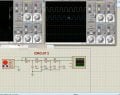
I want to convert rectangular pulse to sin wave. I used cascaded RC circuit to get sinusoidal wave but it is not happening in ltspice. Though in proteus it is. Can anyone please guide me through.
Is it the right way to convert pulse train to sinusoids?
Is it the right way to convert pulse train to sinusoids?
Attachments
-
 396.7 KB Views: 27


