Read from temperature sensor by multiple controller and read a fake temperature

Thread Starter

dades1988

Joined Aug 28, 2022
8
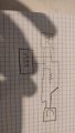
Hi. Currently I have a generic thermocouple TC which is read by a generic C controller (photo AS_IS).
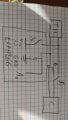
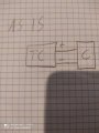
I would like to read the temperature with a max6675 (MAX) and through a relay manage the read temperature of C. That is, (by relay) C have to read the true temperature by TC or read a fake temperature... passing through some resistances (as in photo goal).
Now I am not an electrical engineer, but I would like to understand if I can have problems with dirty reading, short circuit, current return or what else ...

Thanks
 

Attachments

Reloadron

Joined Jan 15, 2015
7,501
The MAX 6675 is designed to read accurately from a Type K thermocouple and only a type K thermocouple and includes CJC (Cold Junction Compensation). I have no idea what a generic thermocouple is? Thermocouples have Type like J, K, T to name a few. The thermocouple wire can't be run through a relay. As long as you switch only your "fake" thermocouple no big deal but switching an actual thermocouple requires some special switching. Type K wire is Chromel + and ALumel -. As drawn I don't quite see what your objective is?

Ron
 

MisterBill2

Joined Jan 23, 2018
18,176
A resistor can not substitute for a real TC because the TC generates a voltage. The fact that the voltage is just a very few millivolts means that relay switching will tend to cause errors due to all of the dis-similar metals in the circuit. If the "fake reading" is a calibration/function check, that is one thing but I predict spending a lot of effort.
To detect thermo-couple failure external high value resistors can supply an external bias voltage, which does not affect the reading unless the TC circuit becomes open. Then the reading goes off the scale either up or down, depending on the bias value.
 

Thread Starter

dades1988

Joined Aug 28, 2022
8
I found that I have a thermistor (10 kohm for 25 degrees celsius) and not a thermocouple. So I ca use a resistance to simulate a high temperature. I can read temperature by a esp8266(ADC pin). Right?
 

Reloadron

Joined Jan 15, 2015
7,501
So you have a 10K thermistor and not a thermocouple. Then just consult a 10K thermistor chart. Switch between the actual thermistor and a fixed resistor for whatever temperature you want to see. A 10K thermistor should be 10,000 Ohms at 25 C (77 F). This is a long way from a generic thermocouple and you cannot use a Max 6675 at all.

Ron
 

Thread Starter

dades1988

Joined Aug 28, 2022
8
So. Can this circuit work?
R1 is resistor for fake temperature. R2 is 10kohm resistor.
S1 and S2 are two relay.
When S1 goes to TH, then S2 is opend and my esp8266 not read temperature and C read true temperature.
When S1 goes to R1, then S2 is closed and my esp8266 read temperature and C read fake temperature.

Otherwise, can I use a better solution?
 

Attachments

Thread Starter

dades1988

Joined Aug 28, 2022
8
MisterBill2
A resistor can not substitute for a real TC because the TC generates a voltage. The fact that the voltage is just a very few millivolts means that relay switching will tend to cause errors due to all of the dis-similar metals in the circuit. If the "fake reading" is a calibration/function check, that is one thing but I predict spending a lot of effort.
To detect thermo-couple failure external high value resistors can supply an external bias voltage, which does not affect the reading unless the TC circuit becomes open. Then the reading goes off the scale either up or down, depending on the bias value.
About "relay switching that cause errors"... is it also true for thermistor?
 

Beau Schwabe

Joined Nov 7, 2019
155
About "relay switching that cause errors"... is it also true for thermistor?
A thermister is probably not going to be as sensitive to relay contacts as a thermocouple, but what it boils down to is the junction of dissimilar metals creating a tiny voltage at the junction that is proportional to temperature known as the "Seebeck effect". Even the same metal looks like dissimilar metals if one has more oxidation than the other.

In a Relay you have a series or chain of different metals from the terminals to the contacts back to the terminals. In an ideal condition the "metal chain" would be the same for both conductive paths and balance itself canceling any voltages produced. However you can't always guarantee this is going to be the case. Any ambient temperature differences may cause one path to have a slightly different temperature that would translate to a net difference in voltage, therefore not cancelling out.
 

Reloadron

Joined Jan 15, 2015
7,501
Using a relay or switch with a thermistor will case, as mentioned above less error. You want to switch between your thermistor and another input to now we see an ESP 8266.

It will look something like this:
Thermistor uC.png

Use the 3.3 Volts out from your ESP 8266. R1 and R2 simulate your fake input or whatever you want to call it. Choose the R2 value accordingly. Write your code accordingly. I strongly suggest you read this example and understand the code. I also suggest you stop changing what you want. I used SW1 but if you are set on a relay then all you need is a single pole double throw (SPDT) relay and drive it however you want.

Ron
 
Top